
Method for producing size selected particles

a technology of selected particles and size, applied in the direction of cobalt carbonates, cobalt compounds, cell components, etc., can solve the problems of reducing the performance of lithium secondary batteries, reducing the tap density, and elusive uniformed sized particles themselves, so as to improve the quality of the product, increase the energy density, and increase the tap density

Active Publication Date: 2014-11-20
UCHICAGO ARGONNE LLC
View PDF1 Cites 9 Cited by
  • Summary
  • Abstract
  • Description
  • Claims
  • Application Information

AI Technical Summary

Benefits of technology

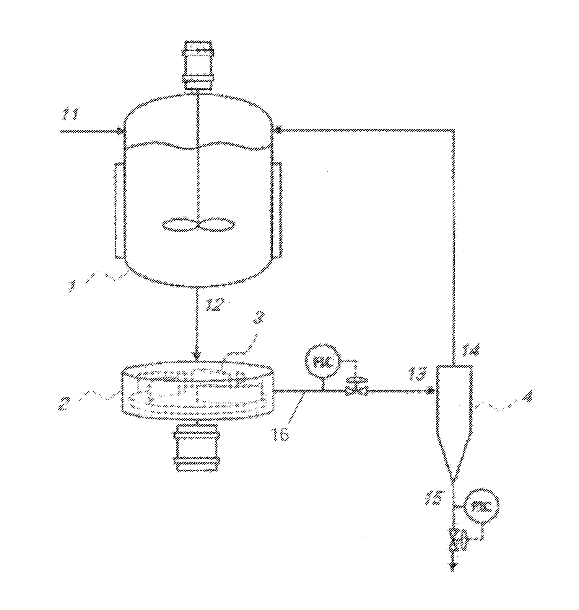
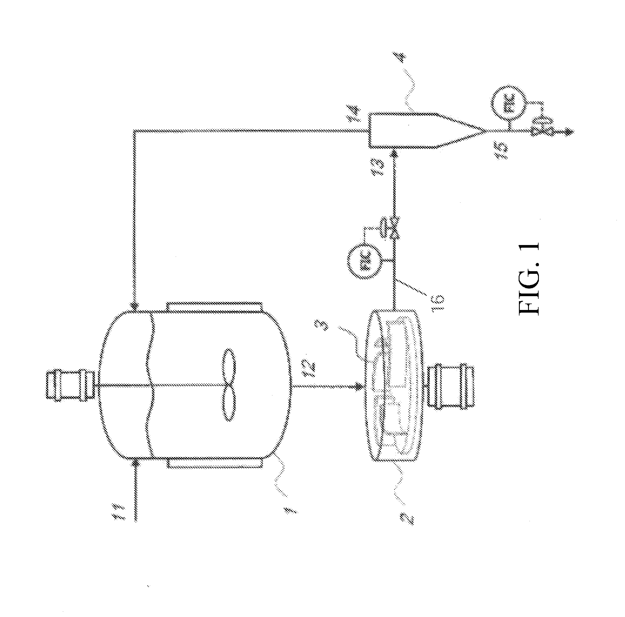
The present invention concerns a system and method for producing particles of different sizes and with desired morphologies. The system includes a continuous stir tank reactor, a centrifugal dispenser, a particle separator, and a solution stream return conduit. The size-selected particles can be produced in a continuous process using post-reactor particle polishing steps. The invention has advantages such as producing tight size-range particles with high tap densities, using recycled reagents, and producing different sized particles with optimal tap density. Additionally, the invention reduces the amount of deionized water and wastewater produced while preparing specific sized particles.

Problems solved by technology

However, consistent generation of uniform sized particles, and the uniformed sized particles themselves remain elusive.
This varying particle size lowers tap density and reduces the performance of lithium secondary batteries.
This in turn leads to a decrease in the cycle life of the battery due to side reactions with electrolyte on the high surface area of the small particles.
Conversely, very large particles (e.g., more than 40 μm) cause problems with cathode coatings and create short circuits in the batteries.
However, sieving does not eliminate particles at the small end of the spectrum.
Sedimentation methods have been employed to eliminate tiny particles, but these methods require time and several repetitions.
This leads to particle loss and particle damage.
However, uniformity of particle sizes between batches is hit or miss.

Method used


Image

  • Method for producing size selected particles
  • Method for producing size selected particles
  • Method for producing size selected particles

Examples


example 1

[0071]A metal solution prepared using nickel sulfate and manganese sulfate, sodium carbonate solution and ammonia solution were fed into a 20 L CSTR with centrifugal disperser and hydrocyclone. The molar flow rate of NiSO4, MnSO4, Na2CO3, and NH4OH are 3.25 mol / hr, 6.5 mol / hr, 10.8 mol / hr, and 1.1 mol / hr, respectively. The ratio of metal solution to alkaline solution is approximately 1:1.2. The residence time in the reactor was approximately 2 hours and reaction temperature was approximately 50° C. This shows that the invention generates size- and morphology-controlled particles (uniform, small and spherical) in the same amount of residence time that state of the art systems take to produce inferior particles (i.e., particles exhibiting varying sizes and morphologies) with the same starting materials. Flow rate of the centrifugal disperser inlet stream was about 1 L / min and the flow rate of desired-size particle solution outlet stream was 25 percent of the tiny particle solution ret...

example 2

[0073]Rotation speed of the centrifugal disperser was varied while all other operations variables maintained as in Example 1. When 1000 RPM was applied to the centrifugal disperser, the average particle size of nickel manganese carbonates produced was about 22 μm. Then the rotation speed was increased to 2000 RPM, the average particle size was about 15 μm. When the rotation speed was increased to 3000 RPM, the average particle size was about 8 μm

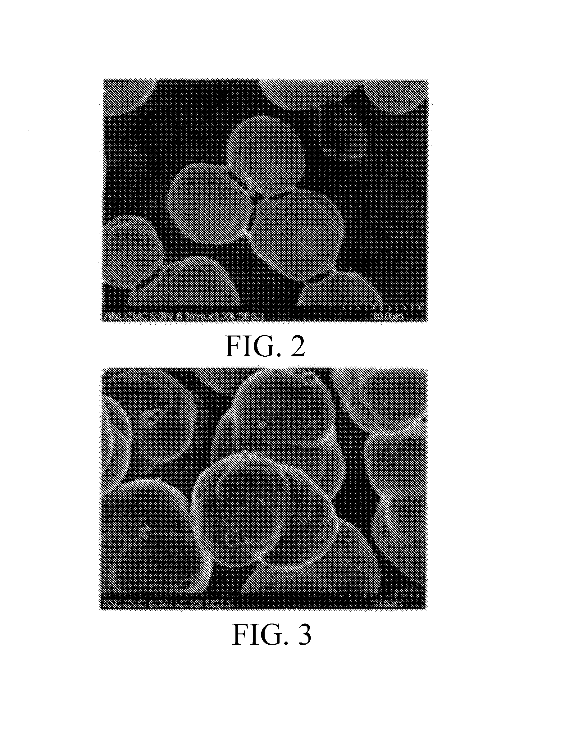
[0074]A density of distribution graph of nickel manganese carbonates produced by the CSTR when the centrifugal disperser's speeds are varied between 1000 and 3000 RPM is illustrated in FIG. 7. SEM images of the electrode active materials which results for the lithium secondary battery by 20 L CSTR with centrifugal disperser and hydrocyclone using these precursors are shown in FIGS. 8-10.

Reduced Wastewater Embodiment

[0075]In the first embodiment of the presently invented system as depicted in

[0076]FIG. 1 and discussed above, the tank reactor ...

example 3

[0080]The reactor tank 1 is fed by a 1M metal solution from feed stream 11 at about 1L / min and by a 0.6M alkaline solution at 2 L / min from ingress line 19. The ratio of metal solution to alkaline solution is maintained at about 1:1.2. The solutions are mixed in the reactor tank 1 and delivered to the centrifugal dispenser 2 via conduit 12. The mixture leaves the reactor tank 1 at a volumetric rate of 3 L / min as opposed to the 4 L / min of the previous embodiment; however, the total number of moles of reactants is the same.

[0081]The mixture from the centrifugal dispenser 2 is provided to the particle separator 4. Like the previous embodiment, a solution containing small particles is returned via return line 14 at a rate of 2 L / min. Thus, the product solution is provided at a rate of 1 L / min, but the solution contains a greater density of the desired size particles. Because a lesser amount of product solution is created, less water is wasted in the recovery of the desired particles.

[008...


PUM


Abstract

The invention provides a system for preparing specific sized particles, the system comprising a continuous stir tank reactor adapted to receive reactants; a centrifugal dispenser positioned downstream from the reactor and in fluid communication with the reactor; a particle separator positioned downstream of the dispenser; and a solution stream return conduit positioned between the separator and the reactor. Also provided is a method for preparing specific sized particles, the method comprising introducing reagent into a continuous stir reaction tank and allowing the reagents to react to produce product liquor containing particles; contacting the liquor particles with a centrifugal force for a time sufficient to generate particles of a predetermined size and morphology; and returning unused reagents and particles of a non-predetermined size to the tank.

Description

CROSS REFERENCE TO RELATED APPLICATIONS[0001]This application claims the benefit of priority to U.S. Provisional Patent Application No. 61 / 823,064, filed on May 14, 2013, currently pending, the contents of which are hereby incorporated by reference.CONTRACTUAL ORIGIN OF THE INVENTION[0002]The United States Government has rights in this invention pursuant to Contract No DE-AC02-06CH11357 between the United States Government and UChicago Argonne, LLC representing Argonne National Laboratory.BACKGROUND OF THE INVENTION[0003]1. Field of the Invention[0004]This invention relates to a method for producing size selected particles, and more particularly this invention relates to a co-precipitation method for consistently producing particles within a predetermined size from a fluid containing relatively tiny and huge particles.[0005]2. Background of the Invention[0006]Certain sized particles as electrode active materials for secondary batteries, or as catalysts for chemical reactions, can op...

Claims


Application Information

Patent Timeline
IPC IPC(8): C01G53/06
CPCC01G53/06C01G45/00C01G51/06C01G53/00C01G53/006C01G53/44C01P2004/03C01P2004/32C01P2004/51C01P2004/52C01P2004/61C01P2006/11H01M4/485H01M4/505H01M4/525H01M2004/021Y02E60/10
Inventor KRUMDICK, GREGORY K.SHIN, YOUNG HOTAKEYA, KANAME
Owner UCHICAGO ARGONNE LLC
Learn More