
Apparatus and Method for Producing Specimens for Electron Microscopy

Active Publication Date: 2014-12-11
ENG ARTS +1
View PDF15 Cites 28 Cited by
  • Summary
  • Abstract
  • Description
  • Claims
  • Application Information

AI Technical Summary

Benefits of technology

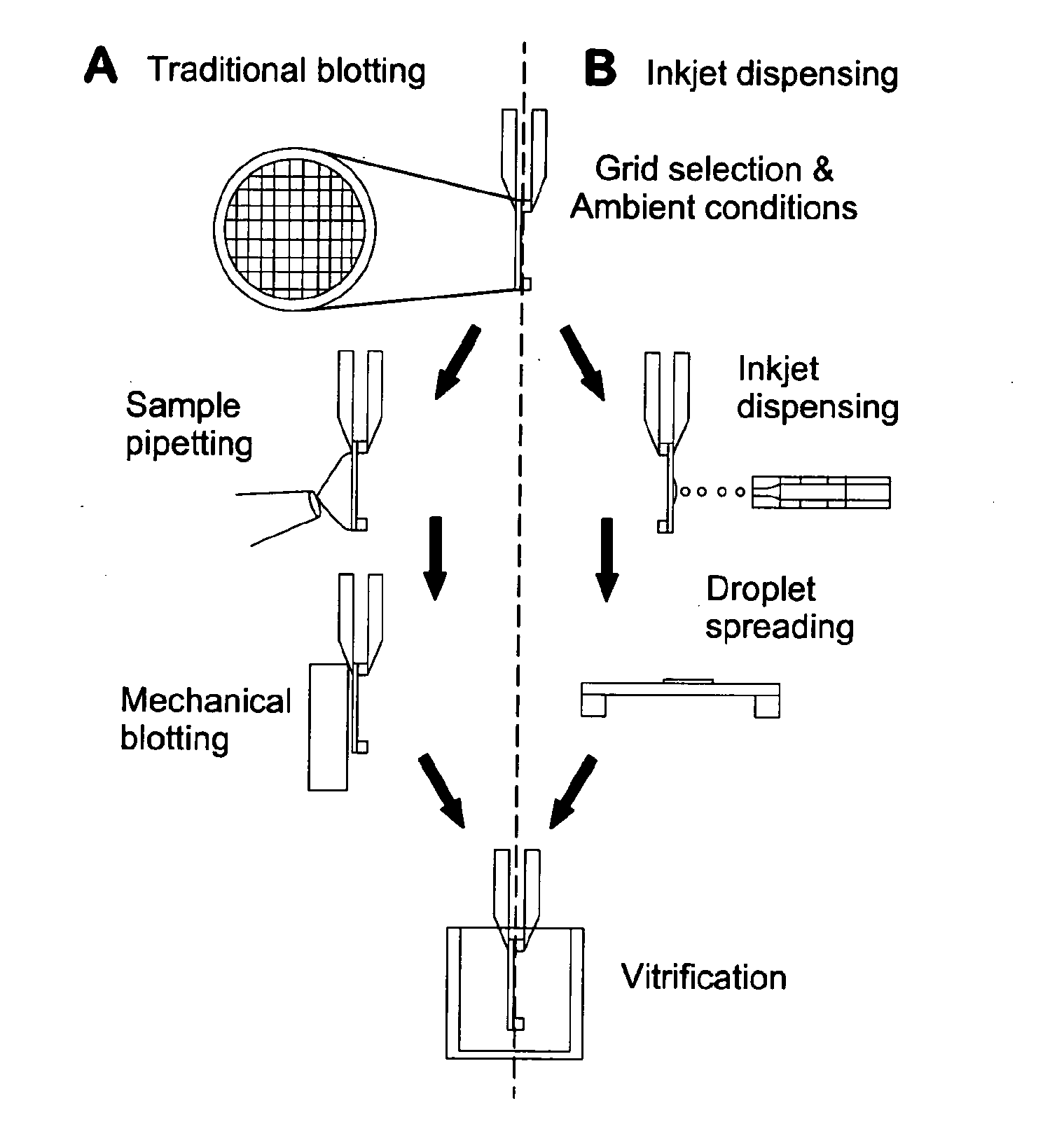
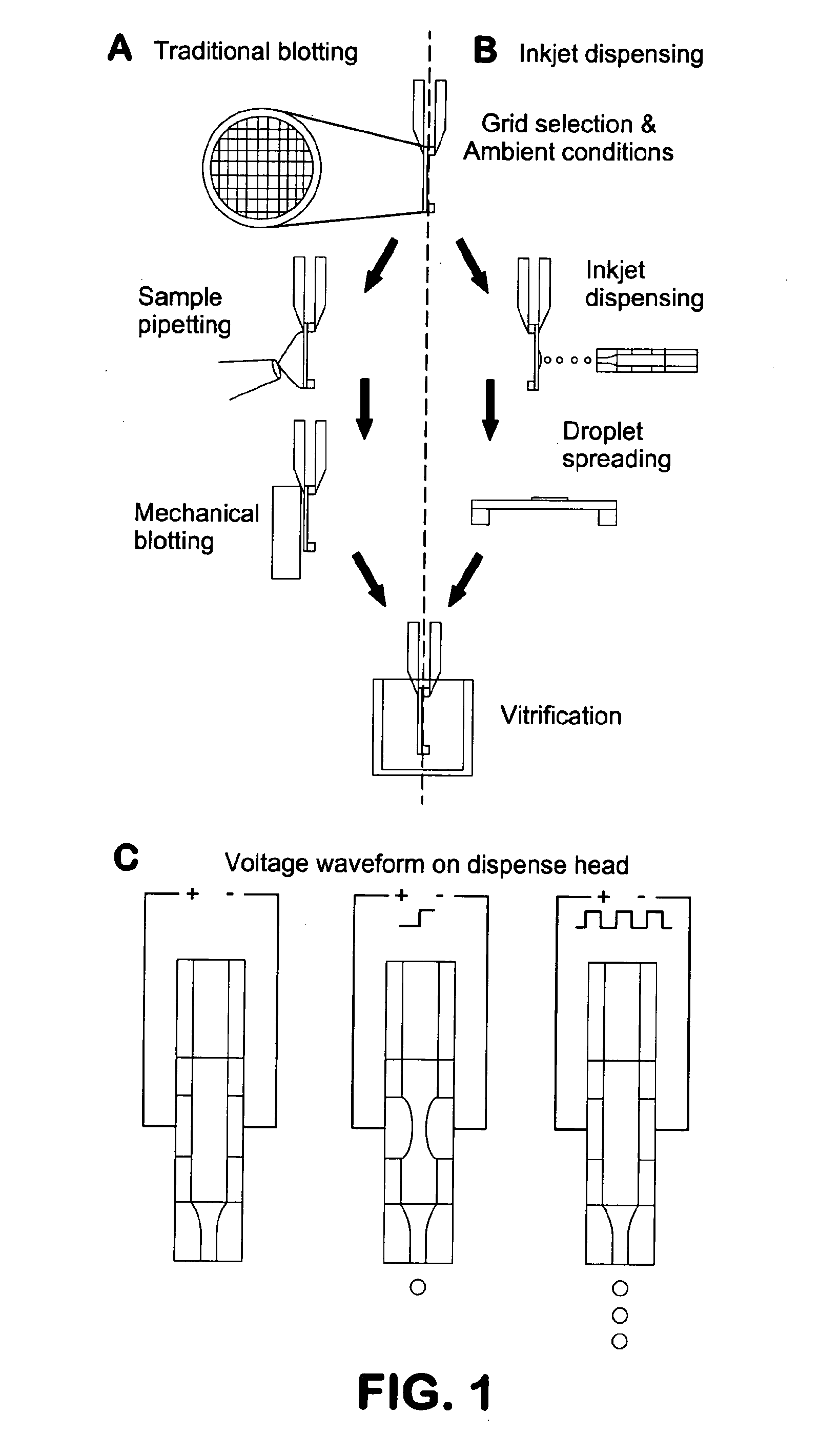
The invention provides methods and devices for preparing frozen vitrified samples for transmission electron microscopy by reducing the volume of sample from microliter scale to picoliter scale. The small volumes of samples can minimize or eliminate the requirement for blotting of excess fluid, and each EM sample grid can be processed to provide an array of specimen locations on a single grid, each specimen location having relatively reproducible characteristics of sample thickness. The inkjet method allows for the ejection of extremely low volumes of sample solution onto discretely addressable locations of the EM sample grid with precise control over sample thickness and expansion. The invention also includes a positioning drive that allows for flexible and precise location of each dispensing element relative to the grid surface.

Problems solved by technology

In preparing EM grids for molecular microscopy, preparation of the sample grid is often the least controlled step in the process.
The result of combining these events is that grid surfaces are not reproducible, either within the same grid or within grids.
Portions of the specimen grid will be too thick for effective penetration by the electron beam, while others will be too thin for proper specimen preservation, while still others will suffer from increases in solute concentrations due to evaporation of water.
Although improving the sample preparation through automating the steps into a more reproducible form, previously described vitrification robots still do not provide the level of sample control necessary for truly reproducible molecular microscopy.

Method used


Image

  • Apparatus and Method for Producing Specimens for Electron Microscopy
  • Apparatus and Method for Producing Specimens for Electron Microscopy
  • Apparatus and Method for Producing Specimens for Electron Microscopy

Examples


example 1

[0038]To test if picoliter to nanoliter dispensing of specimen using piezo-electric inkjet technology can be utilized for cryo-TEM, a system that integrated several modules as shown in FIG. 3. A commercially available piezo-electric dispense head was incorporated with central bore size 24 μm. This head was capable of dispensing discrete specimen droplets of 32 pL; observed in-flight using a stroboscopic LED light and side-view lens / camera system that allowed for viewing dispensed droplets at precise time-points (0-100 μsecs) after droplet generation from the head. Specimen dispense was triggered by software via the accompanying piezo-electric head control module and the number of droplets, frequency and droplet velocity could be modified as desired. Rear-view imaging of the grid at an acquisition rate of 100 Hz allowed for visualizing droplet impact, spreading and evaporation dynamics. The rear-view camera was also used to align the grid with the dispense head and provided a way to ...

example 2

[0039]Using the traditional sample pipetting and blotting technique the entire grid is affected, limiting only one specimen to be evaluated per grid during cryo-TEM study. The ability to precisely align and confine droplets on the substrate could open up the possibility to delivery multiple samples per grid, increasing the throughput of experimentation. Inkjet technology allows for precise positioning of dispense heads in relation to grid substrates, which provides a way to spatially control specimen dispensing on a single EM grid. Spatial targeting was confirmed by fluorescence imaging of the specimens (ex / em: 488 / 520 dye) on the grid. Droplet impact and spreading was further studied in hydrophobic and hydrophilic conditions. For untreated carbon grids the contact angle observed was ˜90°, upon droplet dispensing (25 droplets) and image capture. In contrast, when the carbon grids were treated in an Oxygen / Argon plasma discharge, the contact angles reduced considerably to ˜15°. This ...

example 3

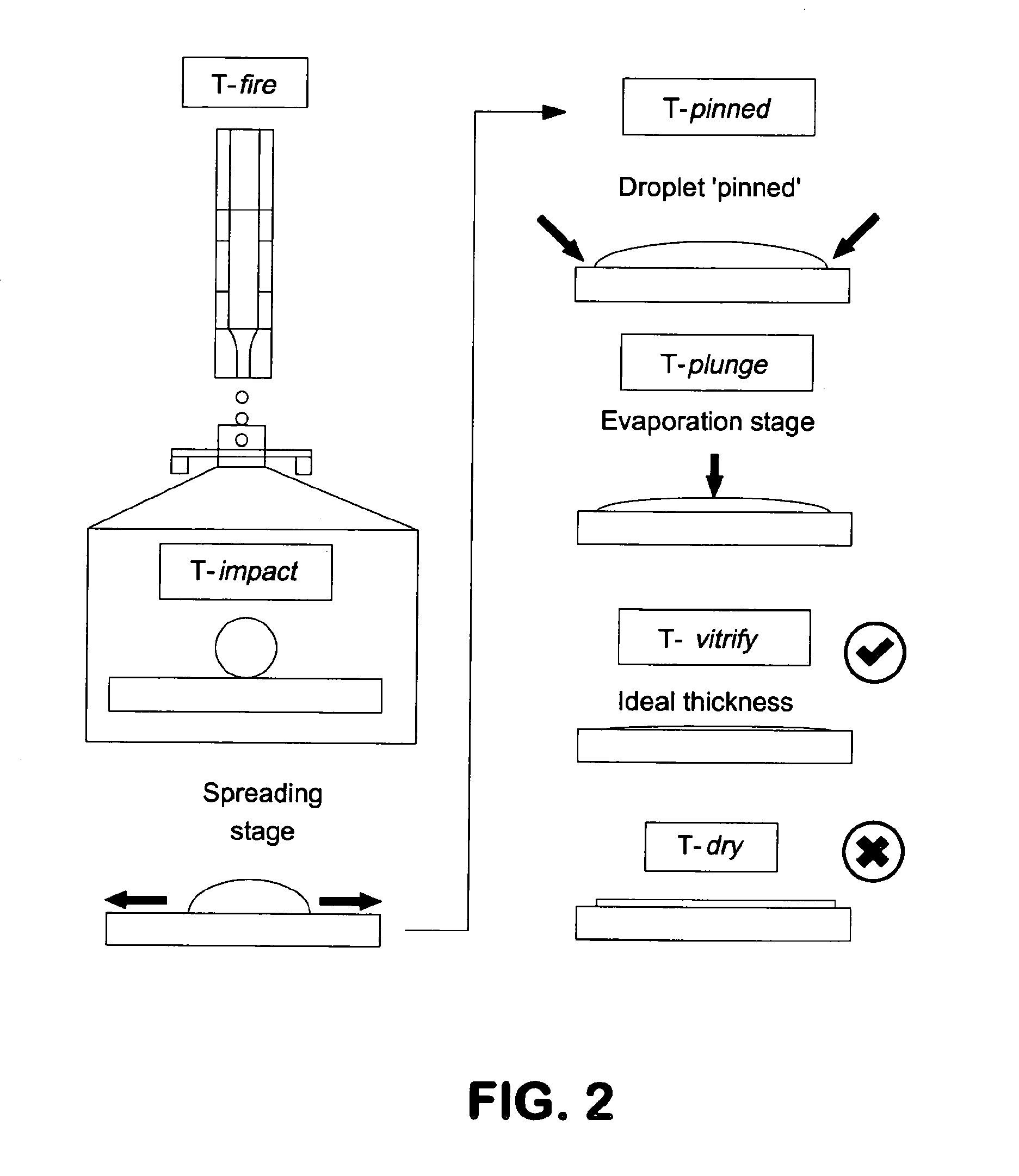
[0040]As one of the goals of this new methodology is to eliminate manual blotting, it is important that the samples on the grid be vitrified at time-points when the sample thickness is suitable for cryo-TEM imaging. This can be accomplished by viewing the droplet dynamics (spreading and drying) on the grid in real-time and triggering the plunge process (for vitrification) at an optimal time-point post-dispensing. At the experimental environment conditions (RH 10%, Temperature 25° C.), a single droplet dries (as observable by rear-view imaging) within 300 msec upon impact onto the grid. Under these conditions, higher number of droplets led to longer drying times (and also larger spreading distances on the grid; data not shown). Also, the repeatability of the droplet dynamics (based on drying times) is high for the droplets dispensed on the grid, allowing for automated plunging events to be accurately timed. In the current system, the plunging event is triggered manually by a hand-ope...


PUM


Abstract

The invention provides methods and devices for preparing frozen vitrified samples for transmission electron microscopy. By reducing the volume of sample from microliter scale to picoliter scale, the requirement for blotting of excess fluid is minimized or eliminated.

Description

BACKGROUND OF THE INVENTION[0001]The following discussion of the background of the invention is merely provided to aid the reader in understanding the invention and is not admitted to describe or constitute prior art to the present invention.[0002]Molecular microscopy is a non-invasive electron imaging technology that uses advanced specimen preparation and imaging methods designed specifically to visualize complex biological samples, under conditions close to their native state. Samples are preserved in a very thin film of solution on an EM grid by vitrification (using an automated cryogenic robot) or by negative stain, and then imaged using a transmission electron microscope (TEM) controlled by automated software that enables sampling of a significant portion of the specimen. High-throughput molecular microscopy combines robotic instruments, automated data collection and processing software, and a relational database into a pipeline to prepare, image, and analyze samples in a repro...

Claims


Application Information

Patent Timeline
IPC IPC(8): G01N1/28G01N1/42H01J37/26
CPCG01N1/28G01N1/42H01J37/261H01J37/26H01J2237/2001H01J2237/2802G01N1/2813
Inventor CARRAGHER, BRIDGETPOTTER, CLINTON S.JAIN, TILAKKAHN, PETERWIKTOR, PETER
Owner ENG ARTS
Learn More