Integrated pump and compressor and method of producing multiphase well fluid downhole and at surface

a multi-phase well and compressor technology, applied in the direction of positive displacement liquid engine, borehole/well accessories, liquid fuel engine, etc., can solve the problems of increasing the complexity of well completion and well control, reducing the efficiency of the pump, and not always being a viable option, so as to facilitate stabilizing heat transfer throughout the system components, improve the efficiency of the compressor, and widen the operating range of gas-volume-fraction (gvf)

Active Publication Date: 2014-12-25
SAUDI ARABIAN OIL CO
View PDF7 Cites 23 Cited by
  • Summary
  • Abstract
  • Description
  • Claims
  • Application Information

AI Technical Summary

Benefits of technology

[0013]Both the pump and compressor are driven by a single motor shaft which includes an internal passageway associated with one of the machineries for reception of the fluid from the other machinery, thereby providing better cooling and greater efficiency of all systems associated therewith.
[0024]The present inventive method is also effective when a portion of the shaft associated with pump is hollow to provide a flow path for gas discharged from the compressor, thereby facilitating stabilizing heat transfer throughout the system components.

Problems solved by technology

In addition, the pump volumetric efficiency is reduced as the gas is filing the impeller vanes.
However, this may not always be a viable option in wells requiring corrosion protection through the use of deep set packers to isolate the annulus from live hydrocarbons.
All these options add complexity to well completion and well control.
This geometry reduces the possibility to trap gas in the stages and hence to gas lock.
Axial pump stages can handle up to 75% free gas, but have poor efficiency compared to mixed flow stages.
Yet, at the current stage, it still has a limited capability to handle liquid.
Two motors are required with this approach, which results in a complex system.
Surface MPP and WGC are costly, complex and many times still suffer from reliability issues.

Method used


Image

  • Integrated pump and compressor and method of producing multiphase well fluid downhole and at surface
  • Integrated pump and compressor and method of producing multiphase well fluid downhole and at surface
  • Integrated pump and compressor and method of producing multiphase well fluid downhole and at surface

Examples


Embodiment Construction

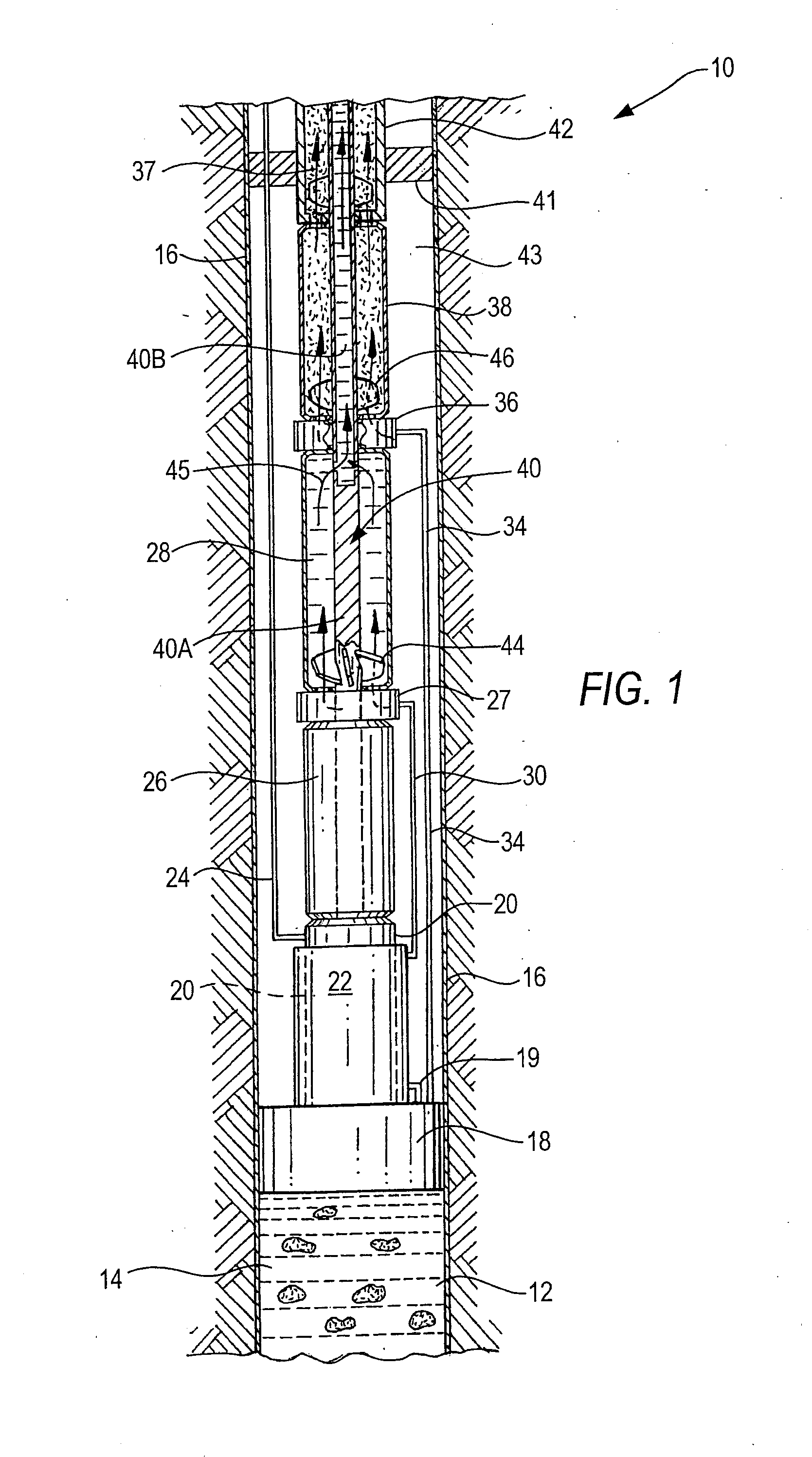
[0030]One preferred embodiment of the present invention is illustrated in FIG. 1, which is an elevational view, partially in cross-section, of a combination liquid pump / gas compressor 10 shown downhole in a vertical orientation. A typical portion of a well 12 contains a liquid / gas mixture 14, and is provided with a suitable casing sleeve 16 which extends downhole to where the liquid / gas mixture 14 exists.

[0031]Downstream of the liquid / gas supply is liquid / gas separator 18, which is shown schematically in FIG. 1, and which may be any one of several known types of separators, such as those which utilize gravity, shrouds, centrifugal or rotary gas separation, or gas-liquid cylindrical cyclonic, in-line separation technology, or the like.

[0032]Downstream of separator 18 is drive motor 20, encased in cooling jacket 22. The motor 20 can be powered from the surface by known means, including electric power or the like delivered to drive motor 20 by power cable 24. Production fluids are dire...


PUM


Abstract

An integrated system is disclosed to handle production of multiphase fluid consisting of oil, gas and water. The production stream is first separated into two streams: a liquid dominated stream (GVF<5% for example) and a gas dominated stream (GVF>95% for example). The separation can be done through shrouds, cylindrical cyclonic, gravity, in-line or the like separation techniques. The two streams are then routed separately to pumps which pump dissimilar fluids, such as a liquid pump and a gas compressor, and subsequently recombined. Both pumps are driven by a single motor shaft which includes an internal passageway associated with one of the pumps for reception of the fluid from the other pump, thereby providing better cooling and greater overall efficiency of all systems associated therewith. A method for providing artificial lift or pressure boosting of multiphase fluid is also disclosed.

Description

RELATED CASE[0001]This application claims priority under 35 U.S.C. 119, 120 on applicants' Provisional Application No. 61 / 838,761 filed Jun. 24, 2013 which application is incorporated herein by reference.BACKGROUND OF THE INVENTION[0002]1. Field of the Invention[0003]The present invention relates to a system and method for producing multiphase fluid (i.e., oil, gas and water) either downhole or at surface using artificial lift methods such as Electric Submersible Pump (ESP), Wet Gas Compressor (WGC) and Multi-Phase Pump (MPP).[0004]2. Description of the Related Art[0005]Downhole artificial lift or surface pressure boosting are often required to increase hydrocarbon production and recovery. The production fluids are often a mixture of gas, oil and water. In the case of an oil well, the operating pressure downhole can be below the bubble point pressure or the well can have gas produced from the gas cap together with the oil. For gas wells, the gas is often produced with condensate and...

Claims


Application Information

Patent Timeline
Patent Type & Authority Applications(United States)
IPC IPC(8): F04B25/00E21B43/34
CPCE21B43/34F04B25/00E21B43/38F04B23/04F04B47/02E21B43/128F04D31/00F04D13/12F05D2240/61F04B47/06E21B21/002
Inventor XIAO, JINJIANGSHEPLER, RANDALL ALAN
Owner SAUDI ARABIAN OIL CO
Why Eureka
Try Eureka