Phase Contrast Imaging Using Patterned Illumination/Detector and Phase Mask

a phase contrast and detection device technology, applied in imaging devices, instruments, nuclear engineering, etc., can solve the problems of phase ring, loss of low spatial frequency in imaging process, phase ring represents a second disadvantage, etc., to achieve the effect of reducing the disadvantages of zernike pc, increasing photon efficiency, and reducing the cost of operation

Inactive Publication Date: 2015-02-26
CARL ZEISS X RAY MICROSCOPY
View PDF5 Cites 46 Cited by
  • Summary
  • Abstract
  • Description
  • Claims
  • Application Information

AI Technical Summary

Benefits of technology

[0011]The invention uses a modified phase shifting mask with increased efficiency. Using this configuration, the disadvantages of Zernike PC can be minimized and the configuration can lead to an improved imaging methodology potentially with drastically reduced artifacts and more than one order of magnitude gain in photon efficiency, in some examples. Moreover, it can be used to yield a direct representation of the sample's phase contrast...

Problems solved by technology

Scanning Zernike PC suffers from similar imaging artifacts as in the wide-field case.
These artifacts are mainly due to the ring-shaped phase shifting mask, leading to the loss of low spatial frequencies in the imaging process and a subsequent haloing around sample feature edges.
In the scann...

Method used


Image

  • Phase Contrast Imaging Using Patterned Illumination/Detector and Phase Mask
  • Phase Contrast Imaging Using Patterned Illumination/Detector and Phase Mask
  • Phase Contrast Imaging Using Patterned Illumination/Detector and Phase Mask

Examples


first embodiment

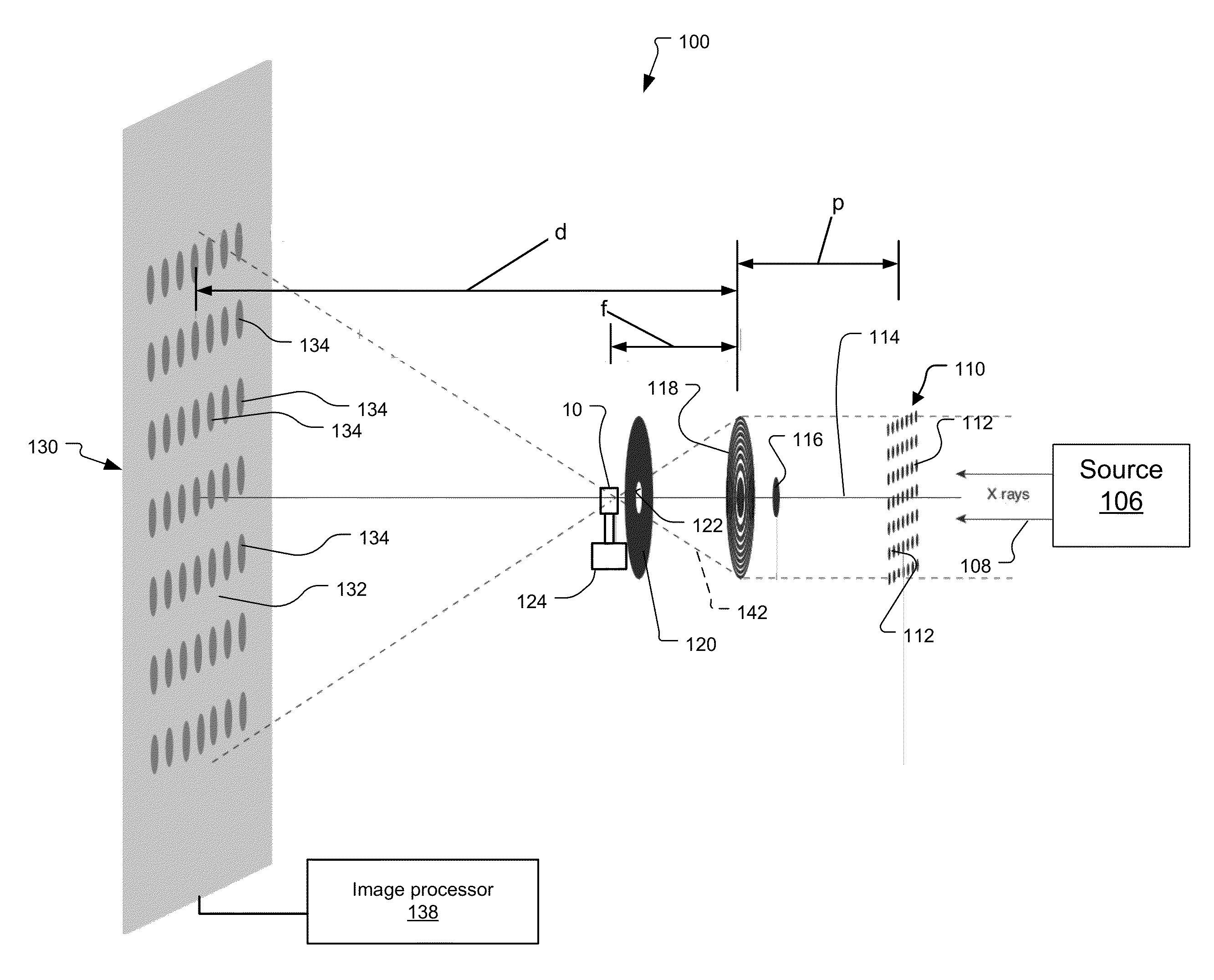
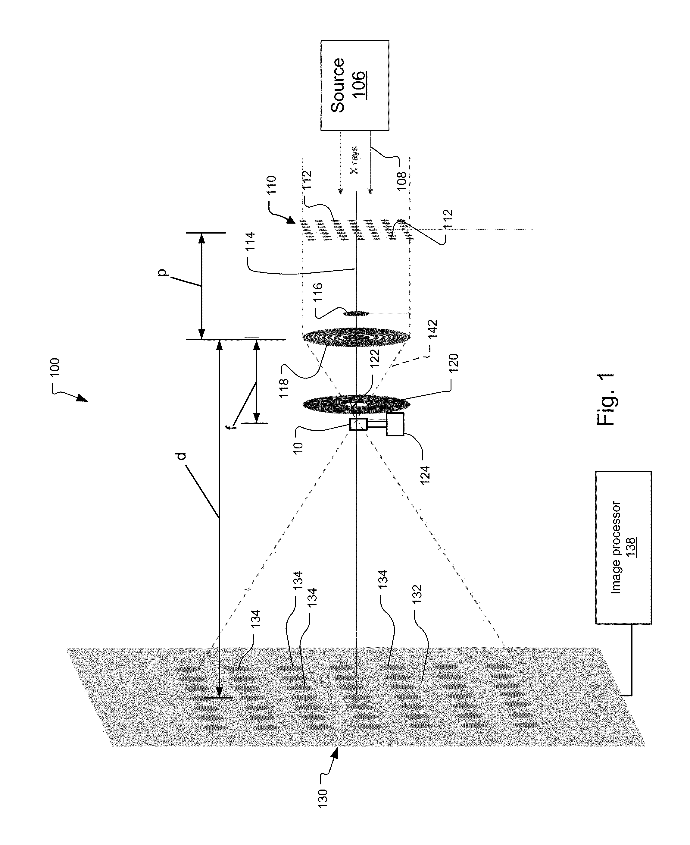
[0030]FIG. 1 shows a scanning imaging microscope 100 constructed according to the present invention.

[0031]Radiation 108 is generated by a radiation source 106. Typically, this radiation is intrinsically narrowband radiation or broadband radiation that is filtered by a bandpass filter to be narrowband. In the illustrated example, the radiation is generally collimated.

[0032]In the preferred embodiment, the radiation 108 is x-ray radiation having an energy between 0.2 keV and 100 keV. Some specific examples of the source 106 include a sealed tube x-ray source, a rotating anode x-ray source, a micro-focus x-ray source, metal jet micro-focus x-ray source, or a synchrotron radiation source. Some of these sources include an integrated or separate collimator.

[0033]In the example of an electron microscope, the source 106 generates radiation that is an electron beam, having an energy between 10 keV and 1 MeV.

[0034]A phase plate or mask 110 phase shifts a portion of the radiation so that the r...

second embodiment

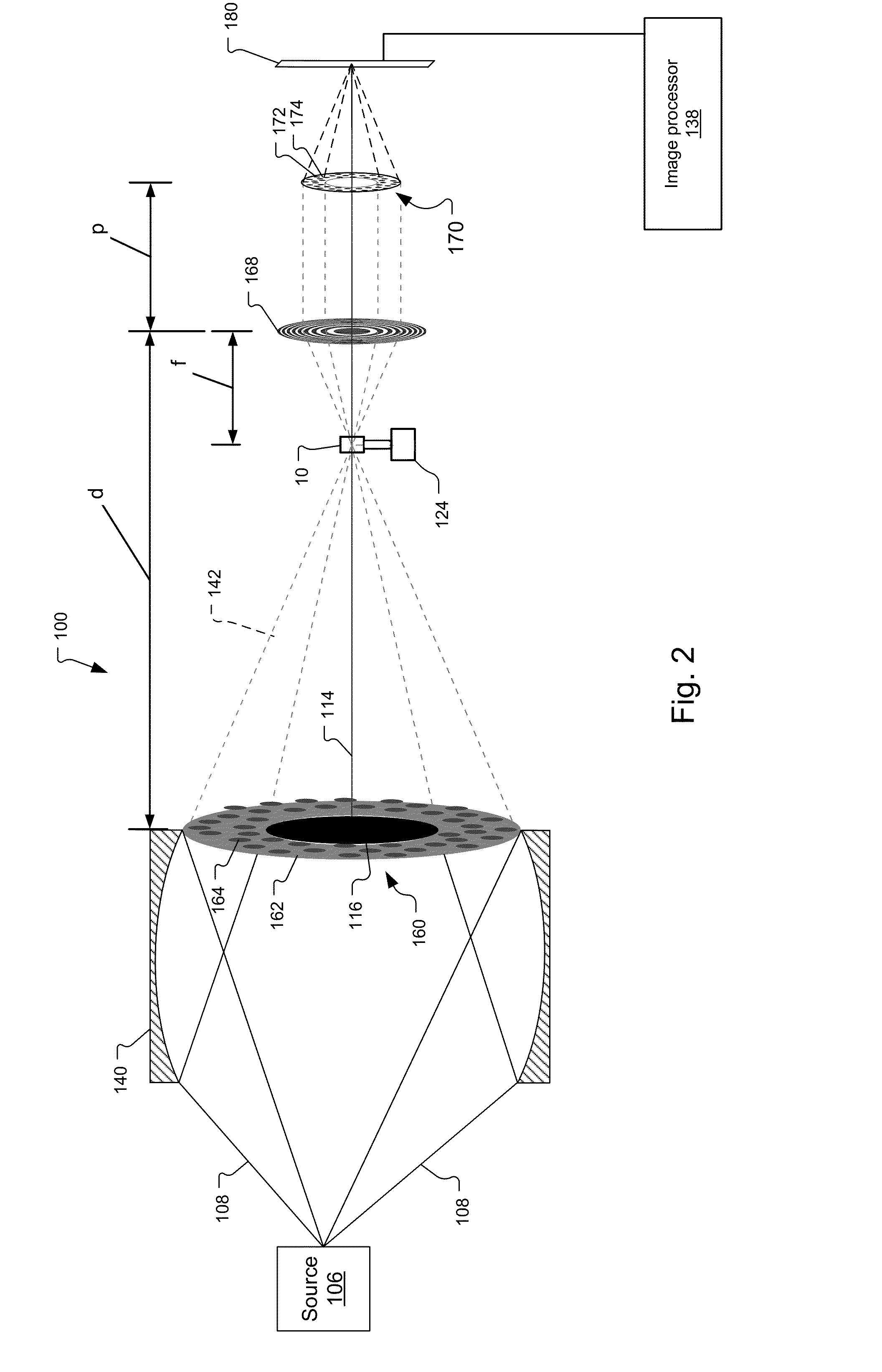
[0057]FIG. 2 shows a wide-field imaging microscope 100 constructed according to the present invention.

[0058]Radiation 108 is similarly generated by a radiation source 106. The figure shows radiation 108 radiating out as from a point source, which is consistent with radiation generated from a laboratory source such as a sealed tube source, a rotating anode x-ray source, metal jet micro-focus source, or a micro-focus x-ray source, in examples.

[0059]But here also, in other examples, the radiation 108 is generated by a synchrotron or other x-ray radiation source. In this case, a more collimated beam would be provided.

[0060]In other embodiments, the radiation 108 is an electron beam.

[0061]If a laboratory x-ray source is used, then typically a reflective condensing element is often preferred. In the illustrated example, a cylindrical capillary condenser 140 collects the radiation radiating from the source 106 and focuses the radiation.

[0062]A converging cone of radiation 142 directed towa...


PUM


Abstract

A modified phase shifting mask is used to improve performance over traditional Zernike phase contrast imaging. The configurations can lead to an improved imaging methodology potentially with reduced artifacts and more than one order of magnitude gain in photon efficiency, in some examples. Moreover, it can be used to yield a direct representation of the sample's phase contrast information without the need for additional specialized post-acquisition image analysis. The approach can be applied to both wide-field and scanning configurations by using a phase mask including a pattern of phase elements and an illumination mask, having a pattern of holes, for example, that corresponds to a pattern of the phase mask.

Description

RELATED APPLICATIONS[0001]This application claims the benefit under 35 USC 119(e) of U.S. Provisional Application No. 61 / 869,187, filed on Aug. 23, 2013, which is incorporated herein by reference in its entirety.BACKGROUND OF THE INVENTION[0002]X-rays, due to their high penetration power and possibility of an extended depth-of-field due to their short wavelength, are ideally suited for imaging thick and embedded soft and biological materials. In some energy ranges and / or samples including low-Z elements, phase contrast (PC) significantly dominates over absorption in transmission imaging. Thus, features that are difficult or impossible to observe in absorption contrast can be effectively studied in phase contrast mode.[0003]Various methods of phase contrast imaging exist. Zernike PC was developed by Frits Zernike (see F. Zernike, “Das Phasenkontrastverfahren bei der mikroskopischen Beobachtung.” Z. Techn. Physik. 16, 454-457 (1935)) for wide-field optical microscopy using a phase shi...

Claims


Application Information

Patent Timeline
IPC IPC(8): G01N23/20G21K7/00G01N23/04
CPCG01N23/20075G21K7/00G01N23/04G21K2207/005G01N23/041
Inventor HOLZNER, CHRISTIANFESER, MICHAEL
Owner CARL ZEISS X RAY MICROSCOPY
Why Eureka
Try Eureka