
Anode electrode for aluminum electrolytic capacitor and respective production method

Active Publication Date: 2015-03-05
MICRO ENERGY TECHNOLOGIES GMBH
View PDF1 Cites 12 Cited by
  • Summary
  • Abstract
  • Description
  • Claims
  • Application Information

AI Technical Summary

Benefits of technology

The patent describes a process to increase the surface area of aluminum foil used in aluminum electrodes for aluminum electrolytic capacitors. This is achieved by using a novel coating process called galvanic deposition, which involves depositing aluminum onto the foil from a specific substance class of ionic liquids. The process results in the formation of structures on the foil surface that increase its effective surface area, including microcrystalline granular dendritic, pillar-shaped, and honeycomb-shaped structures. Compared to conventional etching processes, the effective surface area of the foil is increased by at least 200 times. The result is higher power density, which allows for a smaller size of the capacitor and reduces the required volume for implantable medical devices. The thickness of the coated foil is increased, and a reduction in the number of layers used in the capacitor simplifies the production process.

Problems solved by technology

However, a further increase of the effective surface, even by optimization of the etching processes, is typically no longer possible.
Heavier etching generally leads to a loss of mechanical integrity of the material.
The use of a thicker starting material also does not lead to an enlargement of the effective surface, since areas close to the surface are typically lost as a result of the etching process.

Method used


Image

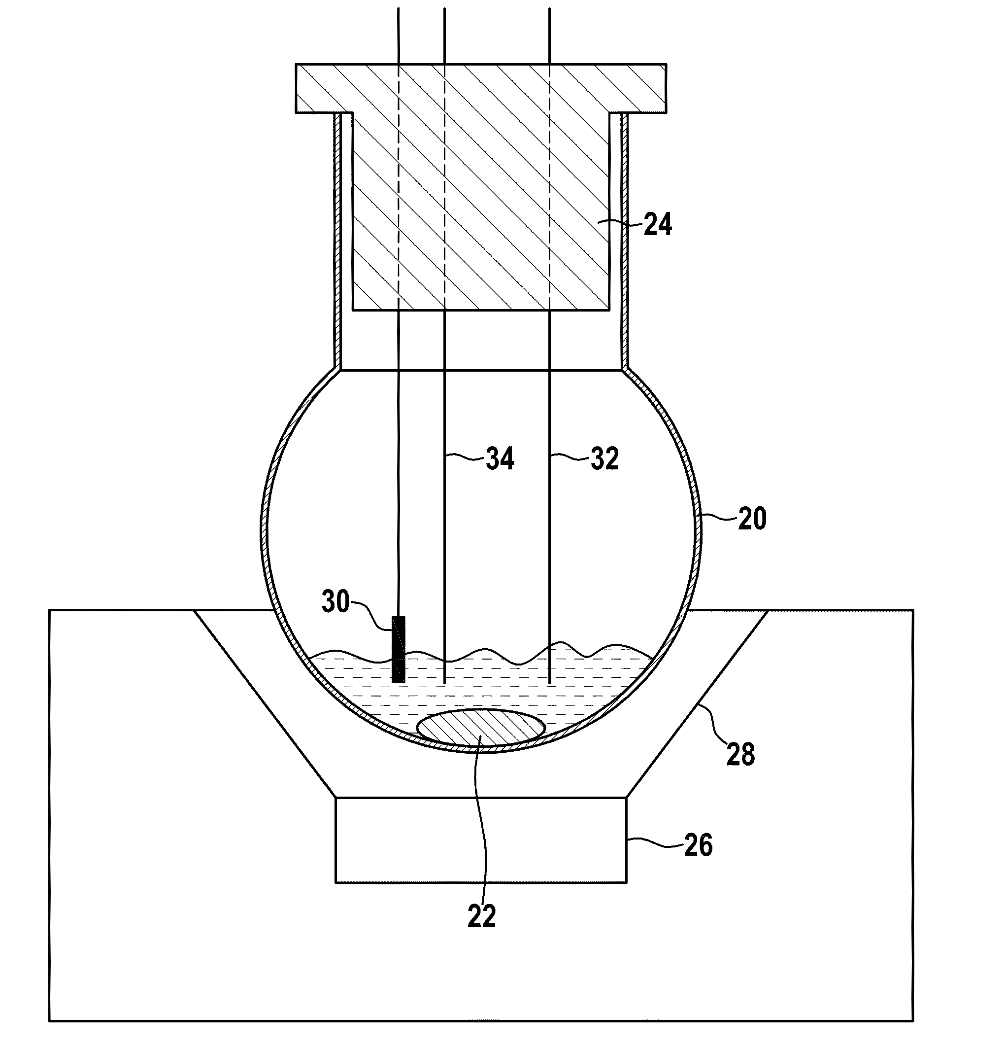
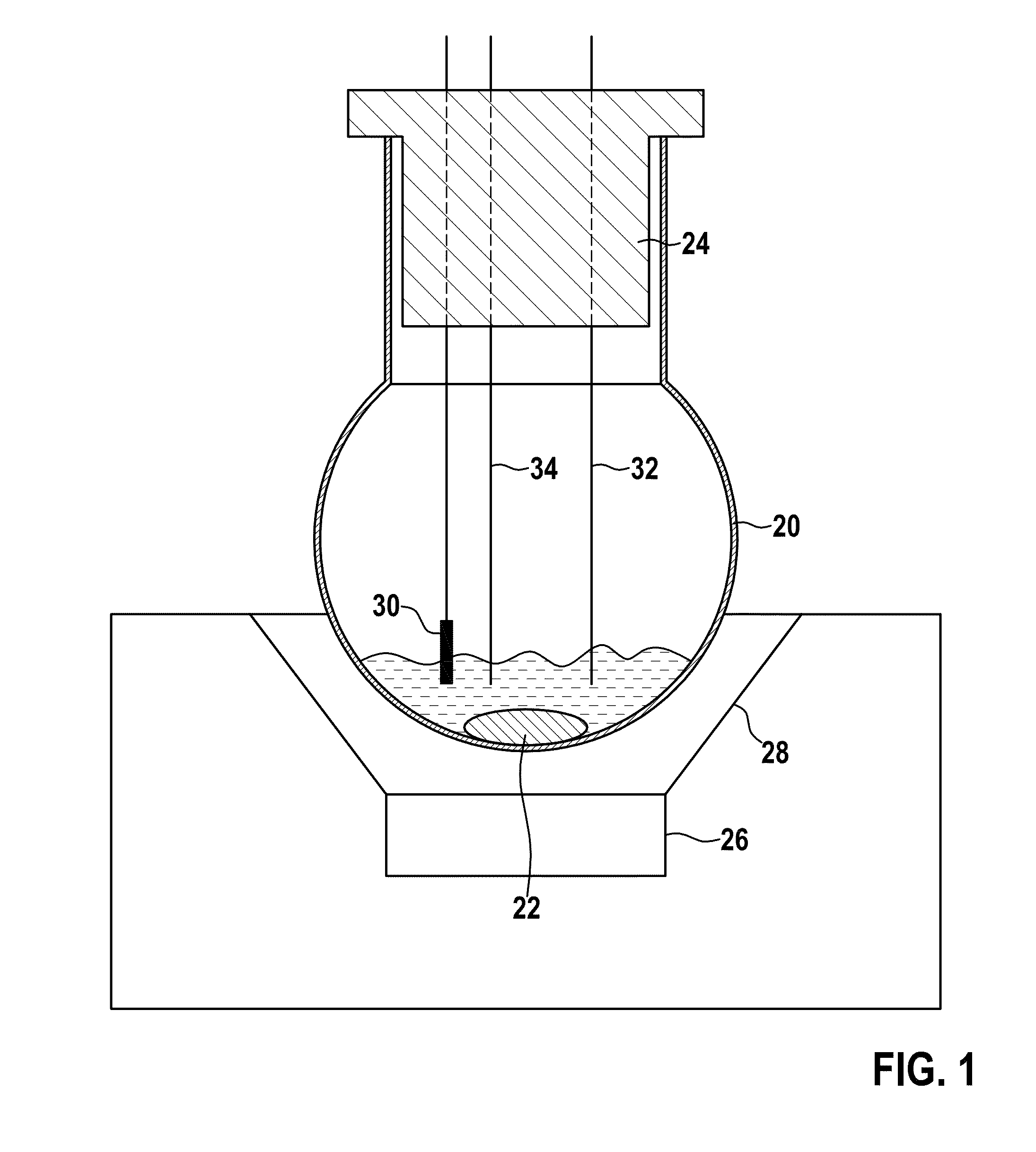
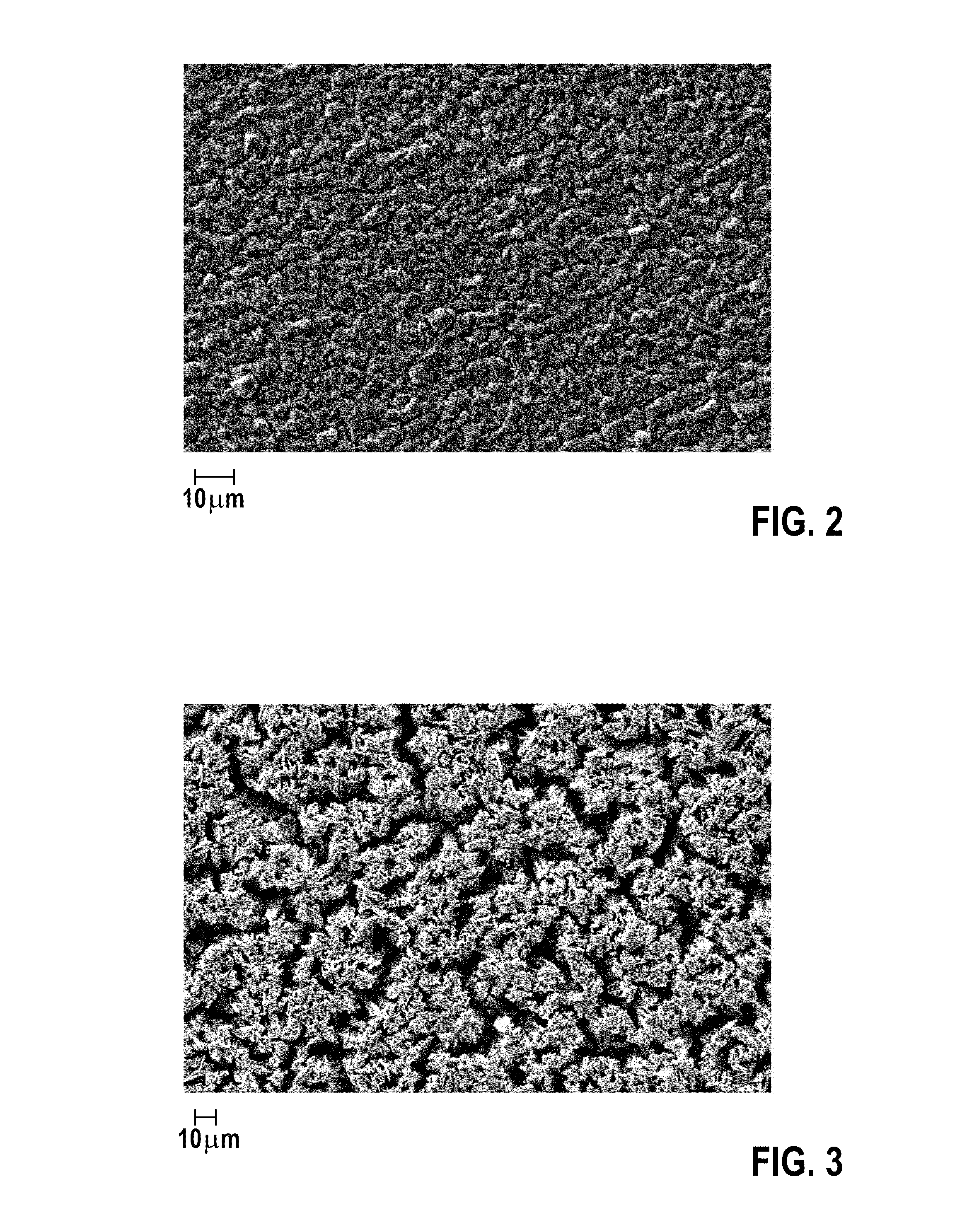
  • Anode electrode for aluminum electrolytic capacitor and respective production method
  • Anode electrode for aluminum electrolytic capacitor and respective production method
  • Anode electrode for aluminum electrolytic capacitor and respective production method

Examples


Embodiment Construction

[0037]The following description is of the best mode presently contemplated for carrying out at least one embodiment of the invention. This description is not to be taken in a limiting sense, but is made merely for the purpose of describing the general principles of the invention. The scope of the invention should be determined with reference to the claims.

[0038]FIG. 8 shows a schematic illustration of a sectional view through a sub-region of an aluminum electrolytic capacitor, which includes an anode electrode, according to at least one embodiment of the invention. As shown in FIG. 8, one or more embodiments may include an anode electrode formed from a first aluminum foil 10 and dielectric 12, and a second aluminum foil 14 (also referred to herein as a cathode foil). In at least one embodiment, the first aluminum foil 10 may be covered on both sides by the dielectric 12 formed from aluminum oxide. In one or more embodiments, the dielectric 12 may be produced by anodic oxidation of t...


PUM


Abstract

An aluminum electrolytic capacitor including an anode electrode, and a method for producing the anode electrode. The method includes providing an aluminum electrolyte including an ionic liquid and an aluminum salt, galvanically deposing an aluminum on an aluminum foil formed from the aluminum electrolyte, and anodically oxidizing a surface of the aluminum foil. The ionic liquid includes a pyrrolidinium cation and a halogenide. The aluminum electrolyte includes 50-70 mol. % of the aluminum salt based on a total substance amount of the ionic liquid and the aluminum salt. The galvanic deposition includes and is based on a deposition temperature ranging from 20° C. to 100° C., a current density ranging from 1 to 100 mA / cm2, an applied potential ranging from −0.1V to −1.0 V based on a potential of an aluminum reference electrode, and a deposition rate ranging from 1 to 50 μm / h.

Description

[0001]This application claims the benefit of U.S. Provisional Patent Application 61 / 872,776 filed on 2 Sep. 2013, the specification of which is hereby incorporated herein by reference.BACKGROUND OF THE INVENTION[0002]1. Field of the Invention[0003]At least one embodiment of the invention relates to a method for producing an anode electrode for an aluminum electrolytic capacitor, an anode electrode obtainable by the method, and also an aluminum electrolytic capacitor containing such an anode electrode.[0004]2. Description of the Related Art[0005]An aluminum electrolytic capacitor is a capacitor of which the anode electrode (also referred to as the anode foil) consists of aluminum, on which a uniform, electrically insulating aluminum oxide layer in the form of a dielectric is produced by anodic oxidation. Generally, a liquid or solid electrolyte forms the cathode of the capacitor. Typically, anhydrous electrolytes are used almost exclusively, of which the conductivity is much lower th...

Claims


Application Information

Patent Timeline
IPC IPC(8): H01G9/00H01G9/045
CPCH01G9/0029H01G2009/0025H01G9/045H01G9/145
Inventor RZANY, ALEXANDERHENSEL, BERNHARDBARTILLA, NICOLASPRETZLAFF, BERND
Owner MICRO ENERGY TECHNOLOGIES GMBH
Learn More