Storage structure of an electrical energy storage cell

a technology of electrical energy storage and storage structure, which is applied in the direction of fuel cells, cell components, electrical apparatus, etc., can solve problems such as failure of batteries, and achieve the effect of preventing diffusion of different dopants

Active Publication Date: 2015-06-18
SIEMENS ENERGY GLOBAL GMBH & CO KG
View PDF3 Cites 0 Cited by
  • Summary
  • Abstract
  • Description
  • Claims
  • Application Information

AI Technical Summary

Benefits of technology

[0015]In addition, it has been found to be appropriate to arrange a porous barrier layer between the shell region and the core region. This barrier layer s...

Problems solved by technology

This leads to aging and subs...

Method used


Image

  • Storage structure of an electrical energy storage cell
  • Storage structure of an electrical energy storage cell
  • Storage structure of an electrical energy storage cell

Examples


Embodiment Construction

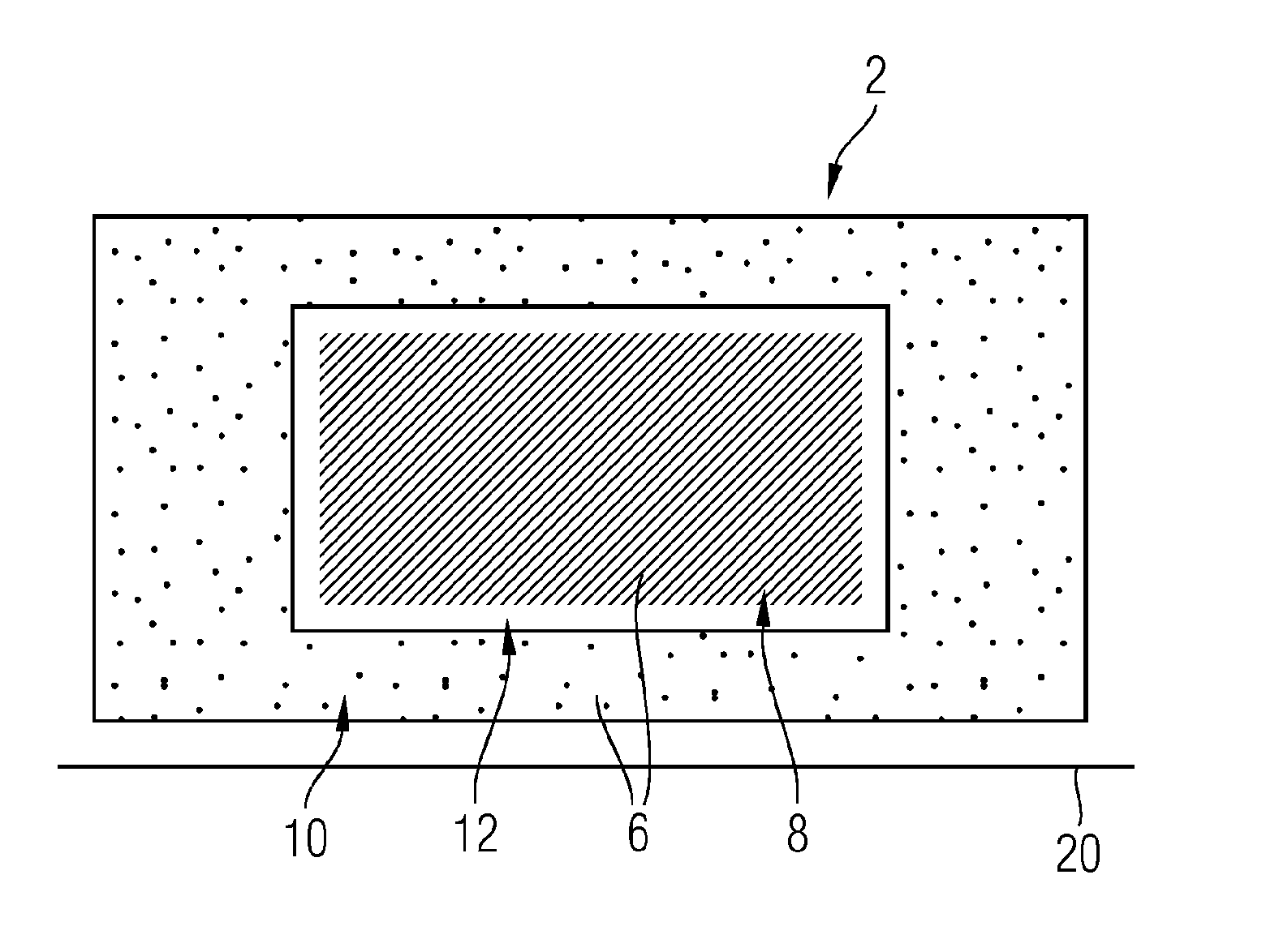
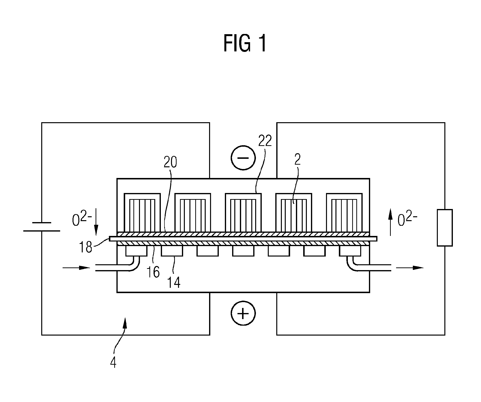
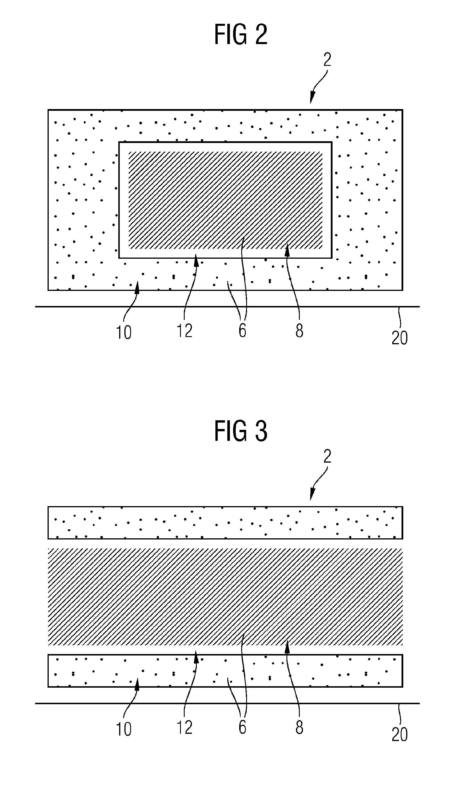
[0023]With reference to FIG. 1, there will first of all be a description, in schematic form, of the way in which a rechargeable oxide battery (ROB) works, to the extent necessary for the present description of the invention. A standard setup of an ROB involves blowing in a process gas, especially air, via a gas supply 14 at a positive electrode, which is also referred to as air electrode 16, with removal of oxygen from the air in the course of discharging (circuit on the right-hand side of the figure). The oxygen passes in the form of oxygen ions O2− through a solid electrolyte 18 that adjoins the positive electrode to a negative electrode 20, which is also referred to as storage electrode. The latter is connected to a porous storage medium via a gaseous redox pair, for example a hydrogen-water vapor mixture. If an impervious layer of the active storage material were to be present on the negative electrode 20, the storage capacity of the battery would thus rapidly be exhausted.

[0024...


PUM


Abstract

A storage structure of an electrical metal-air energy storage cell is provided having an active storage material. The storage structure has a core region and at least one shell region, wherein the material in the core region has a higher porosity than the material of the shell region.

Description

CROSS REFERENCE TO RELATED APPLICATIONS[0001]This application is the US National Stage of International Application No. PCT / EP2013 / 061395 filed 3 Jun. 2013, and claims the benefit thereof. The International Application claims the benefit of German Application No. DE 102012211474.2 filed 3 Jul. 2012. All of the applications are incorporated by reference herein in their entirety.FIELD OF INVENTION[0002]The invention relates to a storage structure of an electrical energy storage cell.BACKGROUND OF INVENTION[0003]Surplus electrical power originating, for example, from renewable energy sources can be stored in the power grid only to a limited degree. This also applies to surplus power which is obtained in fossil power plants when they are running within the optimal economic load range but the power is not being demanded by the consumer from the grid. There are various large-scale storage devices for intermediate storage of this surplus power in relatively large amounts. One of these is, ...

Claims


Application Information

Patent Timeline
IPC IPC(8): H01M4/36H01M4/134H01M4/38H01M4/52H01M12/08
CPCH01M4/366H01M4/52H01M4/134H01M4/38H01M12/08H01M4/625H01M4/8615H01M4/801H01M4/62H01M2004/021Y02E60/10
Inventor BENKERT, KATRINSOLLER, THOMAS
Owner SIEMENS ENERGY GLOBAL GMBH & CO KG
Why Eureka
Try Eureka