Method of manufacturing metal hydroxides and method of manufacturing ITO sputtering target

a technology of metal hydroxide and sputtering target, which is applied in the direction of electrolysis components, vacuum evaporation coatings, coatings, etc., can solve the problems of inability to reduce the cost of waste liquid treatment, the inability to reuse electrolysis solutions, and the inability to reduce the cost of manufacturing. , to achieve the effect of high mass productivity

Inactive Publication Date: 2015-07-16
ULVAC INC
View PDF6 Cites 10 Cited by
  • Summary
  • Abstract
  • Description
  • Claims
  • Application Information

AI Technical Summary

Benefits of technology

[0009]In view of the foregoing, an object of the present invention is to provide a method of manufacturing metal hydroxides with high mass productivity, capable of having a uniform desired particle diameter, and having no need for performing waste liquid treatment of an electrolytic solution, and to provide a method of manufacturing an ITO sputtering target.

Problems solved by technology

Such an electrolytic solution cannot be reused and waste liquid treatment is performed.
Therefore, the cost of the waste liquid treatment is required, and thus the manufacturing cost cannot be decreased.
Moreover, replacement work of the electrolytic solution is required, and mass productivity is significantly impaired.
Further, when the composition of the electrolytic solution is changed, the pH and the temperature of the electrolytic solution become unstable.
The particle diameter of the metal hydroxide is subject to effects of the pH or the temperature of the electrolytic solution, and when the pH of the electrolytic solution is low or the temperature of the electrolytic solution is high, the particle diameter becomes large, and it becomes difficult to obtain the metal hydroxides having a uniform desired particle diameter.

Method used


Image

  • Method of manufacturing metal hydroxides and method of manufacturing ITO sputtering target
  • Method of manufacturing metal hydroxides and method of manufacturing ITO sputtering target
  • Method of manufacturing metal hydroxides and method of manufacturing ITO sputtering target

Examples


Embodiment Construction

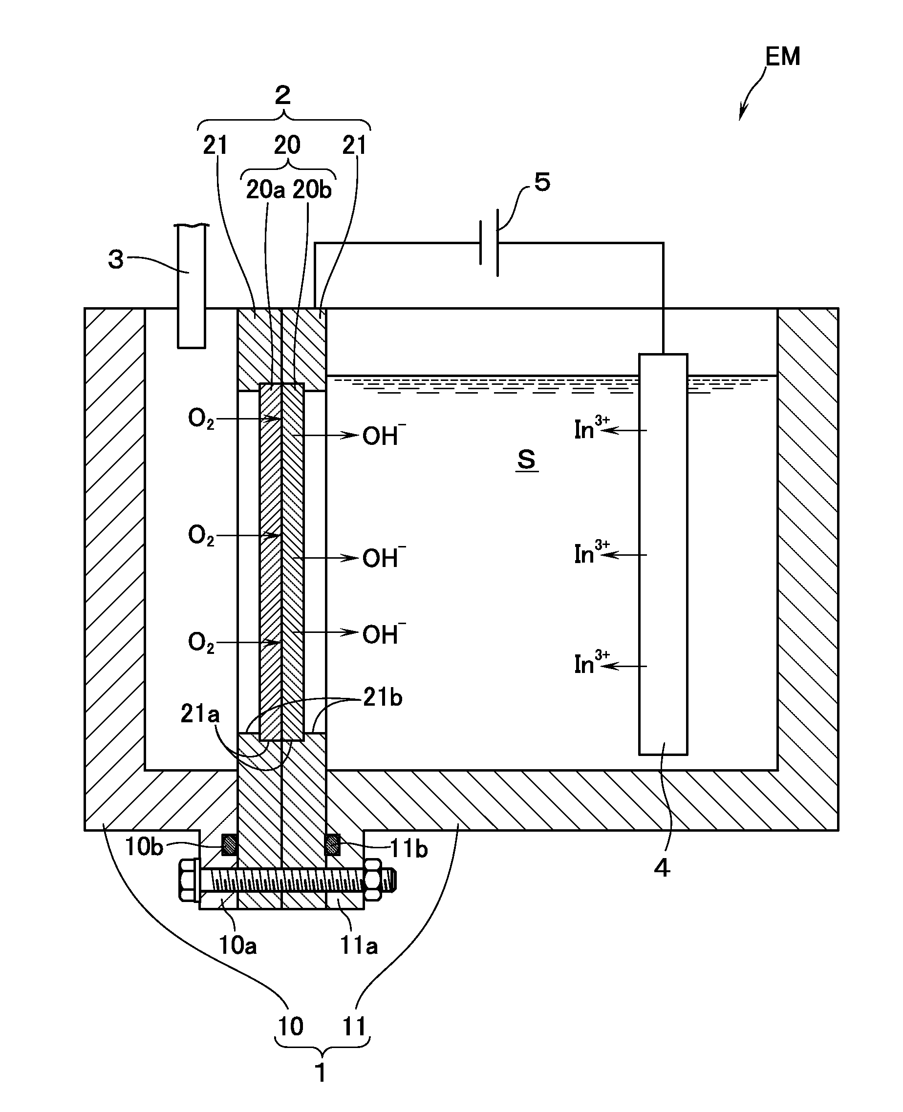
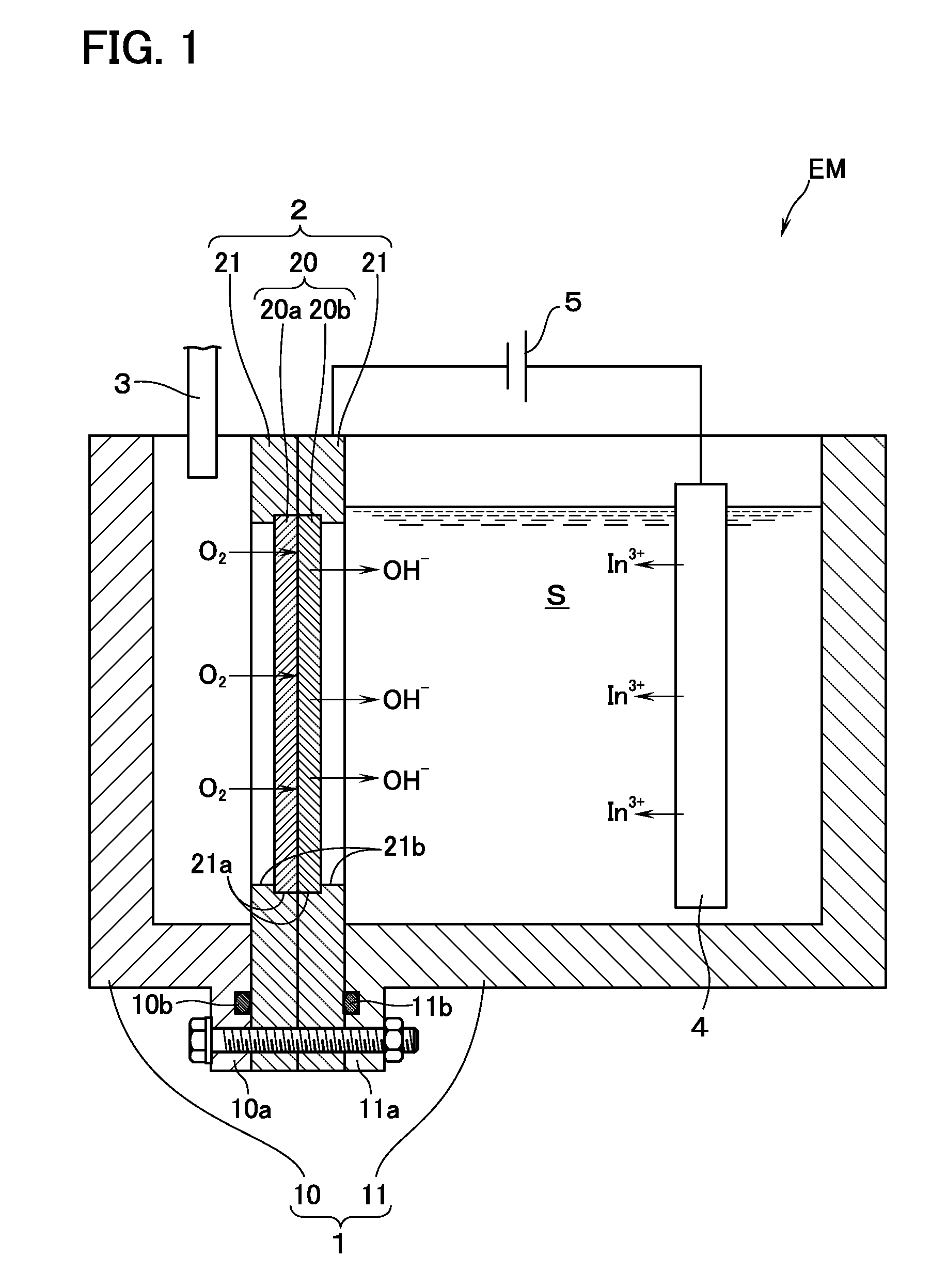
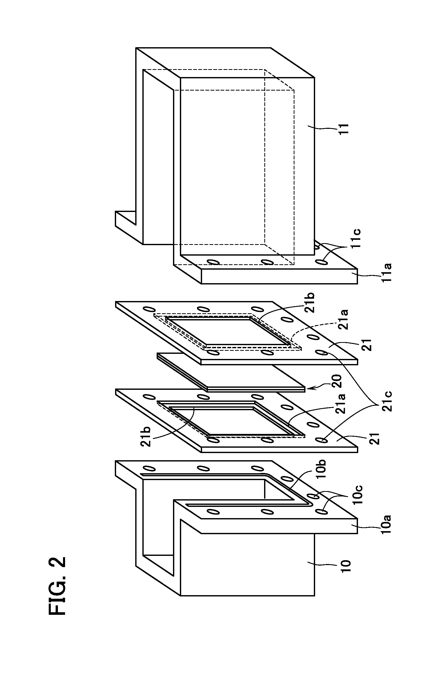
[0018]Referring to FIG. 1, an electrolytic device EM is an electrolytic device used in the present embodiment, and the electrolytic device EM includes an electrolytic bath 1. The electrolytic bath 1 is configured from an air chamber 10 and settling chamber 11. These air chamber 10 and settling chamber 11 have open upper surfaces and open one side surface respectively. Flange portions 10a and 11a are formed at peripheries of the respective one side surface. Packing 10b and 11b are fit into recessed grooves formed in the flange portions 10a and 11a, and can seal an electrolytic solution between the packing 10b and 11b and holding plates 21 described below.

[0019]A cathode 2 is provided in the electrolytic bath 1, and the cathode 2 partitions the electrolytic bath 1. The cathode 2 is configured by a gas diffusion electrode 20, and two sheets of holding plates 21 made of titanium that sandwich the gas diffusion electrode 20. The holding plate 21 plays a role of efficiently energizing the...


PUM

PropertyMeasurementUnit
current densityaaaaaaaaaa
applied voltageaaaaaaaaaa

Abstract

A method of manufacturing metal hydroxides with high mass, and a method of manufacturing an ITO target are provided. A gas diffusion electrode 20 configured such that a hydrophobic gas diffusion layer 20a and a hydrophilic reaction layer 20b are laminated is installed in an electrolytic bath 1 to partition the electrolytic bath. An electrolytic solution S is stored in such a portion of a settling chamber 11 as to face the reaction layer of the partitioned electrolytic bath, and indium 4 is immersed in the electrolytic solution. A voltage is applied between a cathode defined by the gas diffusion electrode and an anode defined by indium. Oxygen is supplied into such a partitioned air chamber 10 as to face the gas diffusion layer to perform electrolysis. Indium hydroxides are thus deposited in the electrolytic solution.

Description

TECHNICAL FIELD[0001]The present invention relates to a method of manufacturing metal hydroxides and a method of manufacturing an ITO sputtering target, and more specifically, relates to a method of manufacturings metal hydroxides used for producing an ITO target.BACKGROUND ART[0002]In flat panel displays such as liquid crystal displays or plasma displays, a transparent conductive film that is an indium tin oxide (hereinafter, referred to as “ITO”) film is used as an electrode. In formation of the ITO film, sputtering devices are widely used in consideration of mass productivity, and the like. As these sorts of sputtering devices, there are ones that apply high-frequency power to an ITO target to form the ITO film (for example, see Patent Document 1).[0003]Patent Document 2 is known to disclose a method of producing such an ITO target. In Patent Document 2, first, an electrolytic solution is stored in an electrolytic bath, indium as an anode and a cathode (for example, iron) are imm...

Claims


Application Information

Patent Timeline
Patent Type & Authority Applications(United States)
IPC IPC(8): H01J37/34C25B1/00
CPCC25B1/00H01J37/3426C25B9/19H01J37/3491C23C14/08C25B11/04Y02E60/36C23C14/3414
Inventor FUJIMARU, ATSUSHIMIMURA, TOSHIFUMIKADOWAKI, YUTAKAMUSHIAKE, KATSUHIKO
Owner ULVAC INC
Why Eureka
Try Eureka