Electromagnetic turbine

a technology of electromagnetic turbines and turbine blades, applied in the direction of wind energy generation, dynamo-electric machines, electrical apparatus, etc., can solve the problems of high current, low voltage and high current, and the general perception of homopolar generators as being extremely inefficient for a long time, so as to reduce contact resistance, reduce the effect of performance and stability over long periods of operation

Inactive Publication Date: 2015-07-30
HERON ENERGY
View PDF7 Cites 7 Cited by
  • Summary
  • Abstract
  • Description
  • Claims
  • Application Information

AI Technical Summary

Benefits of technology

[0075]Another important issue is contact resistance at the liquid-solid interface which can be typically ⅔ of the resistance of the liquid metal contact. Due to various chemical and electrochemical processes occurring in the active zone, various layers are formed at solid surfaces, increasing the resistance and thus reducing contact performance and stability over long periods of operation. A substantial reduction of contact resistance and increased chemical stability can be achieved by a proper choice of thin surface coating material applied

Problems solved by technology

Faraday's generator however was exceedingly inefficient due to counter flows of current which limited the power output to the pickup wires, and the effects of parasitic heating on the copper disc.
Despite various advances in design

Method used


Image

  • Electromagnetic turbine
  • Electromagnetic turbine
  • Electromagnetic turbine

Examples


Embodiment Construction

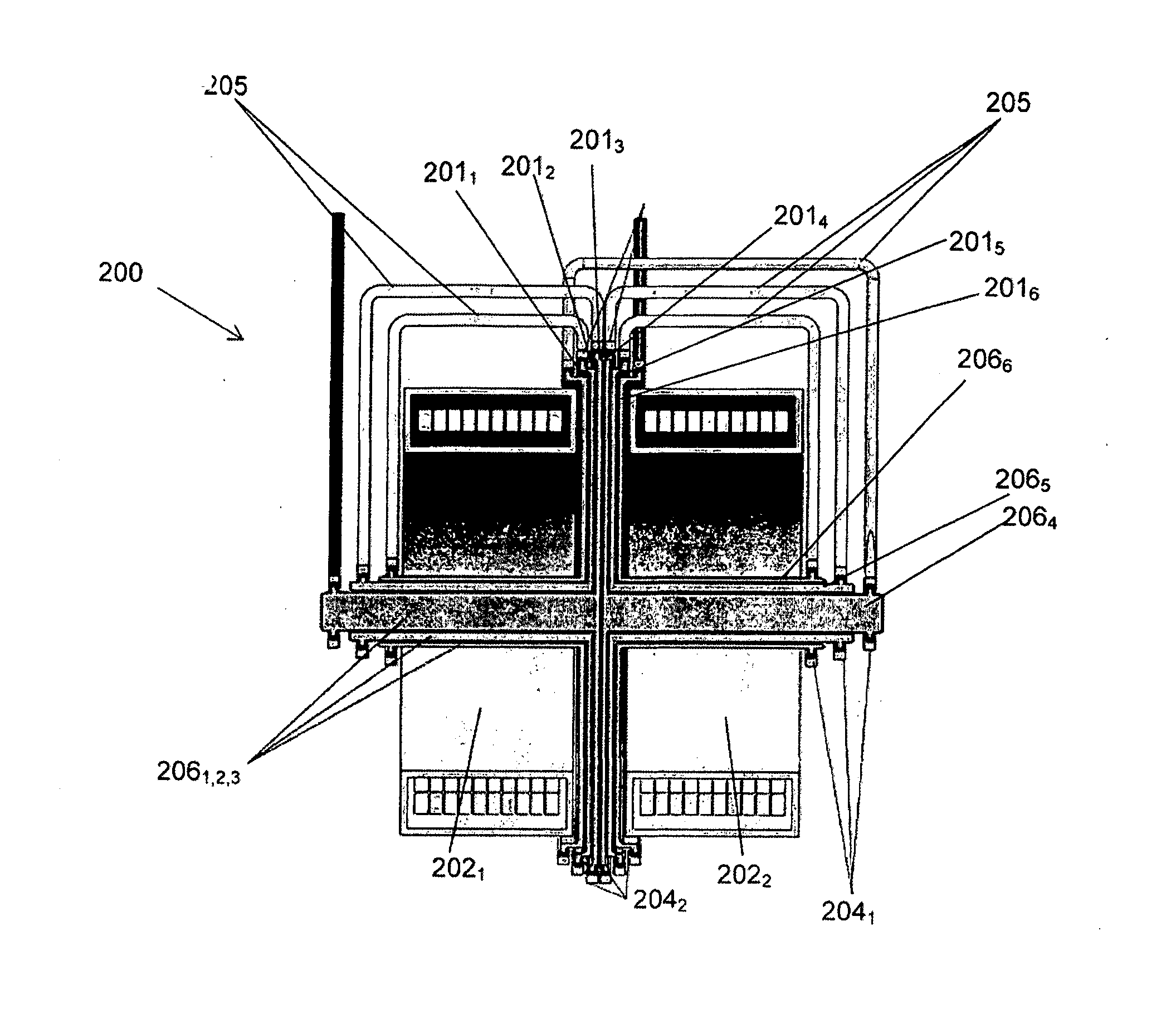
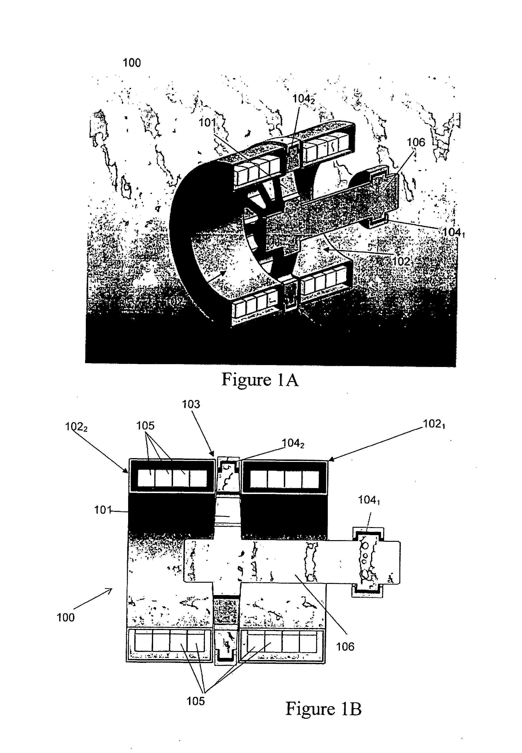
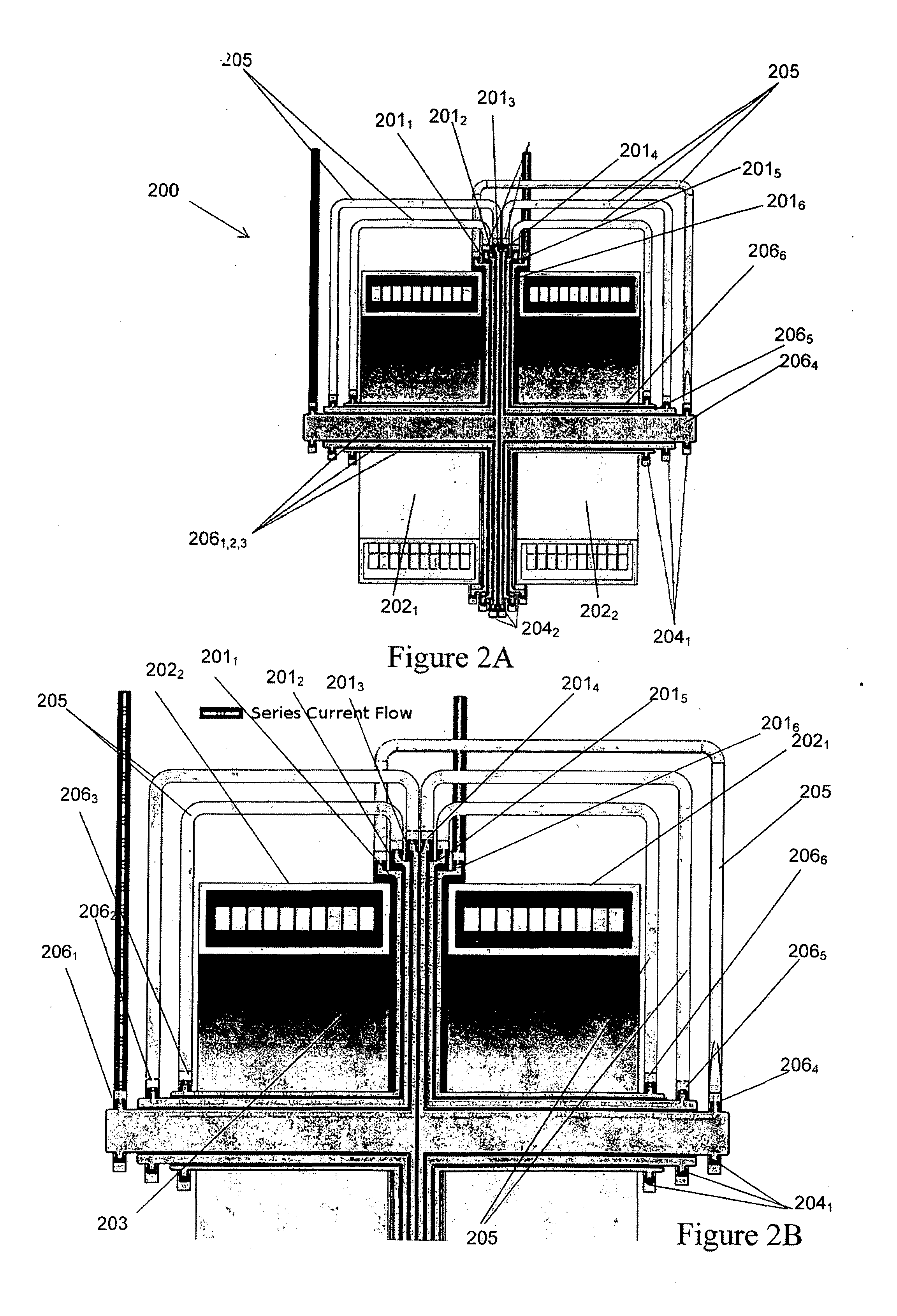
[0215]With reference to FIG. 1A there is illustrated one possible configuration of an electromagnetic turbine for use as a generator 100 according to one embodiment of the present invention. The basic generator layout consists of a conductive disc 101 rotating in a magnetic field that is orientated in the direction of the disc's rotational axis. The magnetic field in the basic layout is created by two superconducting solenoids 1021, 1022 circulating a DC current in the same direction separated by a gap 103. The rotor 101 is positioned in the centre of this gap 103 to utilise the null field area created for the placement of liquid metal brush, 1042. As the disc 101 is rotated by an external power source a voltage is developed between the inner 1041 and outer 1042 liquid metal current collectors. When the arrangement is connected to a suitable electric load current flows from the disc to the load. In this way the mechanical input energy is converted into electrical energy.

[0216]A more...


PUM


Abstract

A generator including a first magnetic assembly and a second magnetic assembly wherein the first and second magnetic assemblies are arranged in parallel for the production of a magnetic field and a null magnetic field region, a rotor positioned between the first and second magnetic assemblies the rotor being coupled to a drive shaft extending through the first and second magnetic assemblies wherein a portion of the rotor is positioned in the null field region, a least one current transfer mechanism coupled to the rotor in the null field region and at least one current transfer mechanism coupled to the shaft, a drive mechanism attached to the shaft, whereby actuation of the drive mechanism causes rotation of the rotor in the magnetic field to produce a electric potential between the first and second current transfer mechanisms.

Description

TECHNICAL FIELD[0001]The present invention relates to electromagnetic turbines. In particular although not exclusively the present invention relates to electromagnetic turbines for power generation.BACKGROUND ART[0002]One of the fundamental principles of physics is the relationship between electricity and magnetism. This relationship was first observed in the mid-1800s when it was noted that current passing through a simple bar conductor, induces a magnetic field perpendicular to the direction of current flow. As a result of the induced magnetic field, each of the moving charges, which comprises the current, experiences a force. The force exerted on each of the moving charges generates torque on the conductor proportional to the magnetic field.[0003]The above discussed basic interactions between electric and magnetic fields are the basic scientific principles which underpin electric motors and generators. One of the simplest forms of electric generator was first exemplified by Micha...

Claims


Application Information

Patent Timeline
IPC IPC(8): H02K55/06H02K13/00H02K47/14H02K3/28H02K1/12
CPCH02K55/06H02K3/28H02K13/003H02K47/14H02K1/12H02K16/00H02K19/20H02K7/116H02K7/183H02K31/04H02K47/04Y02E10/72Y02E40/60H02K1/06H02K3/02H02K7/20H02K21/24H02K55/00
Inventor GUINA, ANTEKELLS, JOHNLABES, KURTSERCOMBE, DAVIDLISSINGTON, TONYFUGER, RENEMATSEKH, ARKADIYGERONIMO, CESIMIRO PAULINO FABIAN
Owner HERON ENERGY
Why Eureka
Try Eureka