Surface modified overhead conductor

a technology of overhead conductors and modified surfaces, which is applied in the direction of non-insulated conductors, power cables, cables, etc., can solve the problems of limited line capacity, more electrical losses in the conductor, damage to the conductor or the accessories of the line, etc., and achieve the effect of reducing the operating temperature of the conductor

Active Publication Date: 2015-08-20
GENERAL CABLE TECH CORP
View PDF5 Cites 13 Cited by
  • Summary
  • Abstract
  • Description
  • Claims
  • Application Information

AI Technical Summary

Benefits of technology

[0011]Accordingly, it is an object of the present invention to provide an overhead conductor that contains a heat radiating agent that, when tested in accordance to ANSI C119.4-2004, reduces the operating temperature of the conductor compared to the temperature of the same conductor without the heat radiating agent. The heat radiating agent can be incorporated directly into the conductor or coated on the conductor. Preferably, the operating temperature is reduced by at least 5° C.
[0013]A yet further object of the present invention provides methods for coating an overhead conductor with an inorganic, non-white, flexible coating that reduces the operating temperature of the conductor compared to the temperature of the same conductor without the heat radiating agent.

Problems solved by technology

The ampacity of a line is limited by the maximum safe operating temperature of the bare conductor that carries the current.
Exceeding this temperature can result in damage to the conductor or the accessories of the line.
Higher current and temperature leads to higher electrical resistance, which, in turn, leads to more electrical losses in the conductor.
Both FR 2971617 and WO 2007 / 034248 require white coatings that are not desirable due to glare and discoloration over time.
Both DE 3824608 and FR 2971617 require polymeric coatings that are not desirable due to their questionable heat and wet aging characteristics.

Method used


Image

  • Surface modified overhead conductor
  • Surface modified overhead conductor
  • Surface modified overhead conductor

Examples


example 1

[0062]Computer simulation studies was performed using different E / A (Emissivity to Absorptivity ratio) values, to measure the reduction in operating temperature of the conductor for the same peak current. The E / A ratios were considered as the surface property of the conductor which is modified by coating. Table 1 tabulates the simulation results for various designs of overhead conductor:

TABLE 1Simulation ResultsSymbolUnitsCase 1Case 2Case 3Case 4Case 5Case 6Case 7Simulation 1: Rail ACSRE / A RatioE / A.5 / .5.3 / .3.9 / .9.7 / .5.8 / .4.9 / .3.9 / .2Number conductors per bundle1111111Peak Current (per conductor)Iamps970970970970970970970Sub-conductor temperatureTc° C.74757370676463Sub-conductor Resistance at TcRohms / mile0.140.140.140.140.140.130.12Power LossPLkW / mile115.37115.60115.03113.92112.68111.52111.03Simulation 2: Curlew ACSRE / A RatioE / A.5 / .5.3 / .3.9 / .9.7 / .5.8 / .4.9 / .3.9 / .2Number conductors per bundle1111111Peak Current (per conductor)Iamps1040104010401040104010401040Sub-conductor temperatureTc°...

example 2

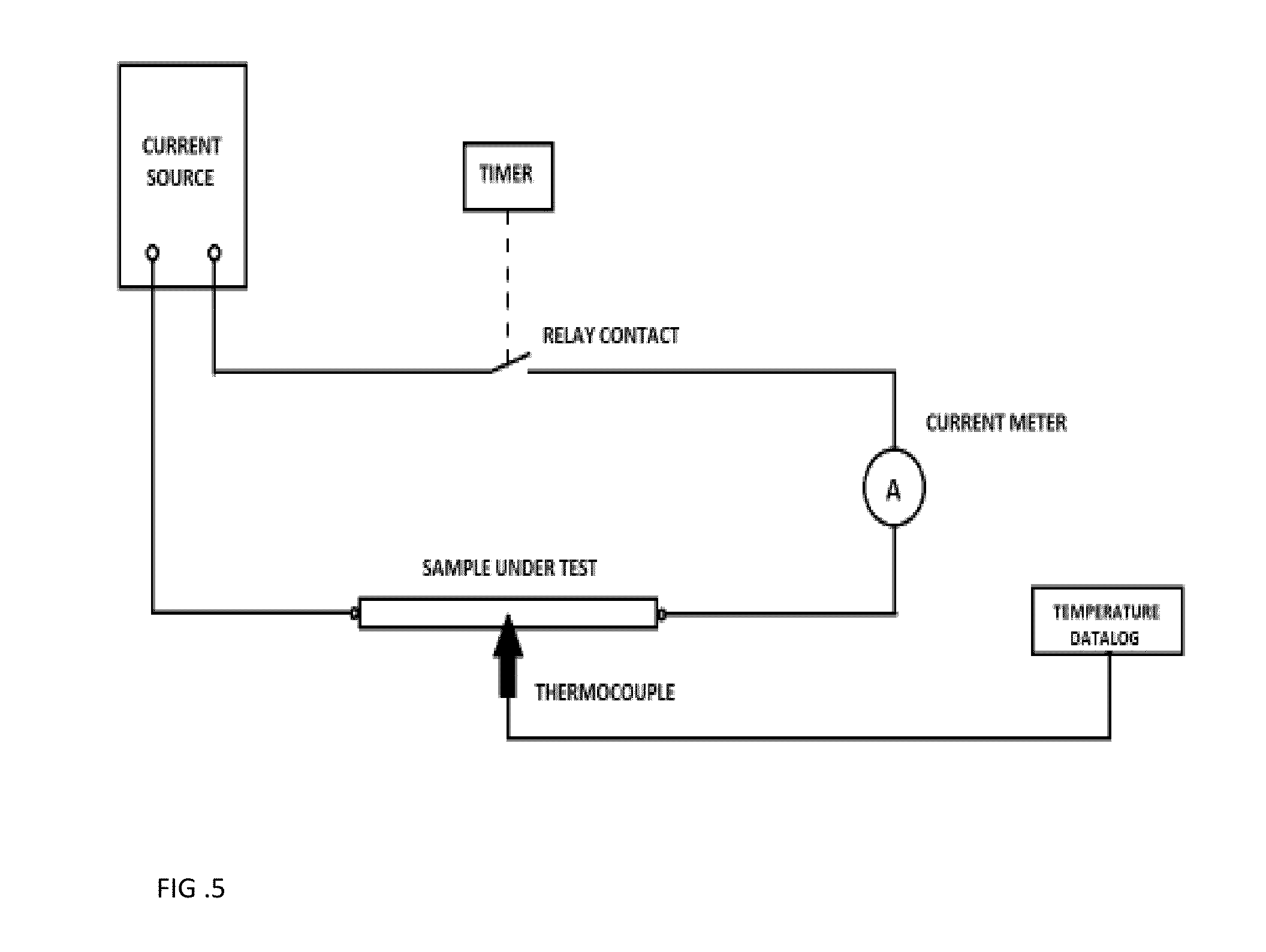
[0063]A coating was prepared by mixing Sodium silicate (20 weight %), Silicon dioxide (37 weight %) with Boron Carbide as a heat radiating agent (3 weight %) and Water (40 weight %). The coating composition is applied to a metal substrate having an emissivity of higher than 0.85. A current is applied through the metal substrate with a 1 mil coating thickness and an uncoated metal substrate to measure the performance improvement of the coating. The test apparatus is shown in FIG. 5 and mainly consisted of a 60 Hz ac current source, a true RMS clamp-on current meter, a temperature datalog device and a timer. Testing was conducted within a 68″ wide×33″ deep windowed safety enclosure to control air movement around the sample. An exhaust hood was located 64″ above the test apparatus for ventilation.

[0064]The sample to be tested was connected in series with an ac current source through a relay contact controlled by a timer. The timer was used to activate the current source and controlled ...

example 3

[0070]Wind effects on temperature rise of the two #4 AWG solid aluminum coated conductors were evaluated at a current of 180 amps. A fan with three speeds was used to simulate the wind and the wind blew directly to the conductor being tested from 2 feet away. The test method circuit diagram is showed in FIG. 7. Both coated and uncoated conductors were tested under 180 amps, solar light, and wind; and the test results are shown in Table 2. The coated conductor was 35.6%, 34.7% and 26.1% cooler than the uncoated when subjected to no wind, low wind, and high wind, respectively. The speed of the wind had a little impact on the coated conductor but a 13% impact on the uncoated.

TABLE 2Wind effect on coated and uncoated conductor's temperature at 180 amps.Temperature Rise (° C. )180 ampsUncoatedCoatedDifferenceDifference (%)No Wind1741126235.6Low Wind101663534.7High Wind88652326.1

[0071]Wind effects on temperature rise of the two #4 AWG solid aluminum conductors were evaluated at 130 amps c...


PUM

PropertyMeasurementUnit
operating temperatureaaaaaaaaaa
heat emissivity coefficientaaaaaaaaaa

Abstract

The present invention relates to a surface modified overhead conductor with a coating that allows the conductor to operate at lower temperatures. The coating is an inorganic, non-white coating having durable heat and wet aging characteristics. The coating preferably contains a heat radiating agent with desirable properties, and an appropriate binder / suspension agent. In a preferred embodiment, the coating has L* value of less than 80, a heat emissivity of greater than or equal to 0.5, and / or a solar absorptivity coefficient of greater than 0.3.

Description

[0001]This application is a continuation of U.S. Non-Provisional patent application Ser. No. 13 / 863,902, filed Apr. 16, 2013, which claims the priority of U.S. Provisional Patent Application Ser. Nos. 61 / 681,926, filed Aug. 10, 2012; 61 / 702,120, filed Sep. 17, 2012; 61 / 769,492, filed Feb. 26, 2013; and 61 / 800,608, filed Mar. 15, 2013; which are incorporated herein by reference.FIELD OF THE INVENTION[0002]The present invention relates to a surface modified overhead conductor with a coating that allows the conductor to operate at lower temperatures.BACKGROUND OF THE INVENTION[0003]As the need for electricity continues to grow, the need for higher capacity transmission and distribution lines grows as well. The amount of power a transmission line can deliver is dependent on the current-carrying capacity (ampacity) of the line. The ampacity of a line is limited by the maximum safe operating temperature of the bare conductor that carries the current. Exceeding this temperature can result ...

Claims


Application Information

Patent Timeline
Patent Type & Authority Applications(United States)
IPC IPC(8): H01B9/00
CPCH01B3/008H01B3/46H01B5/002H01B7/421H01B3/02H01B3/10H01B7/29H01B7/292H01B13/30H01B9/006H01B9/008
Inventor DAVIS, CODY R.RANGANATHAN, SATHISH KUMARANDERSEN, RYANMHETAR, VIJAYTEMPLE, WILLIAM S.SIRIPURAPU, SRINIVASBAKER, GORDONFREESTONE, JAMESDOSS, DENNIS L.
Owner GENERAL CABLE TECH CORP
Why Eureka
Try Eureka