Fabrication of a Malleable Lamella for Correlative Atomic-Resolution Tomographic Analyses

a tomographic analysis and malleable technology, applied in the field of sample formation, can solve the problems of preventing optimal material analysis, catastrophic sample fracture, artifacts in data, etc., and achieve the effect of improving correlative s/tem and apm analysis

Active Publication Date: 2015-09-10
FEI CO
View PDF12 Cites 12 Cited by
  • Summary
  • Abstract
  • Description
  • Claims
  • Application Information

AI Technical Summary

Benefits of technology

[0007]An object of the invention, therefore, is to provide an analytical system that improves correlative S / TEM and APM analysis.

Problems solved by technology

The different tomographic data from either S / TEM or APM used alone prevents optimal material analysis.
In the case where any one or more of the field-evaporating elements on the surface of the APM sample is unable to satisfy the requirements of the field-evaporation equation, the sample may spontaneously evaporate in an uncontrollable fashion (uncorrelated with voltage or laser pulse), leading to artifacts in the data or a catastrophic fracture of the sample.
Additionally, it can be difficult to form a pillar sample with invisible or buried features of the ROI properly positioned within the pillar.
Yet another drawback to correlating S / TEM and APM using a pillar sample is that with the field-of-view of an APM dataset is limited to approximately the inner 50% of the formed pillar shaped sample, a compromise exists between S / TEM data quality and analysis volume in the APM.
Additionally, for those APM runs that make it through the ROI successfully, there are often significant distortions and artifacts in the raw data that cannot be adequately corrected for during the reconstruction or data rendering phase of the analysis.
Another problem with correlative S / TEM and APM tomography is that advanced S / TEM imaging and analytical techniques, such as, for example, holography, differential phase contrast, phase-plate contrast enhancement and even lattice imaging and analysis, are largely incompatible with a pillar-shaped sample.

Method used


Image

  • Fabrication of a Malleable Lamella for Correlative Atomic-Resolution Tomographic Analyses
  • Fabrication of a Malleable Lamella for Correlative Atomic-Resolution Tomographic Analyses
  • Fabrication of a Malleable Lamella for Correlative Atomic-Resolution Tomographic Analyses

Examples


Embodiment Construction

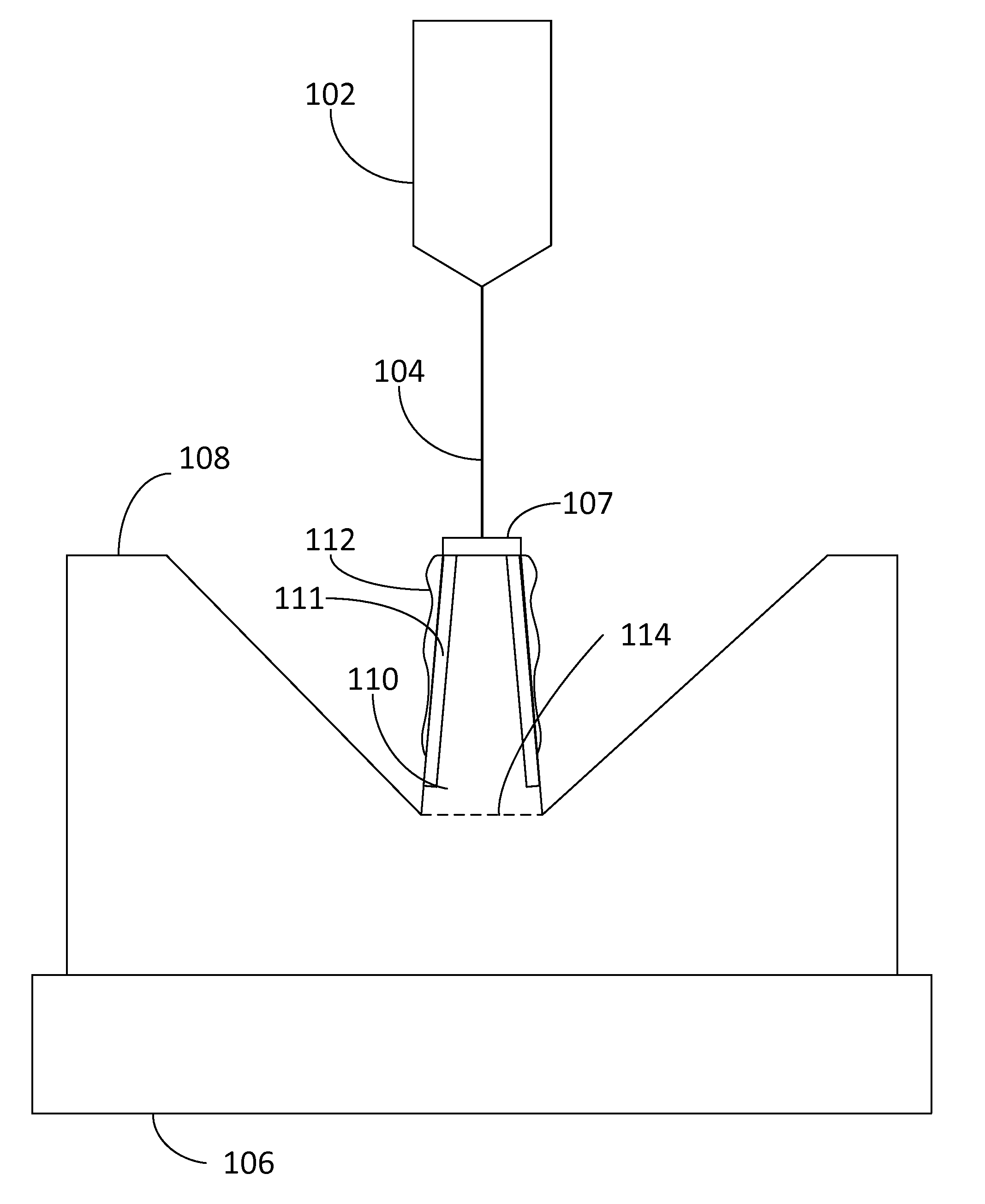
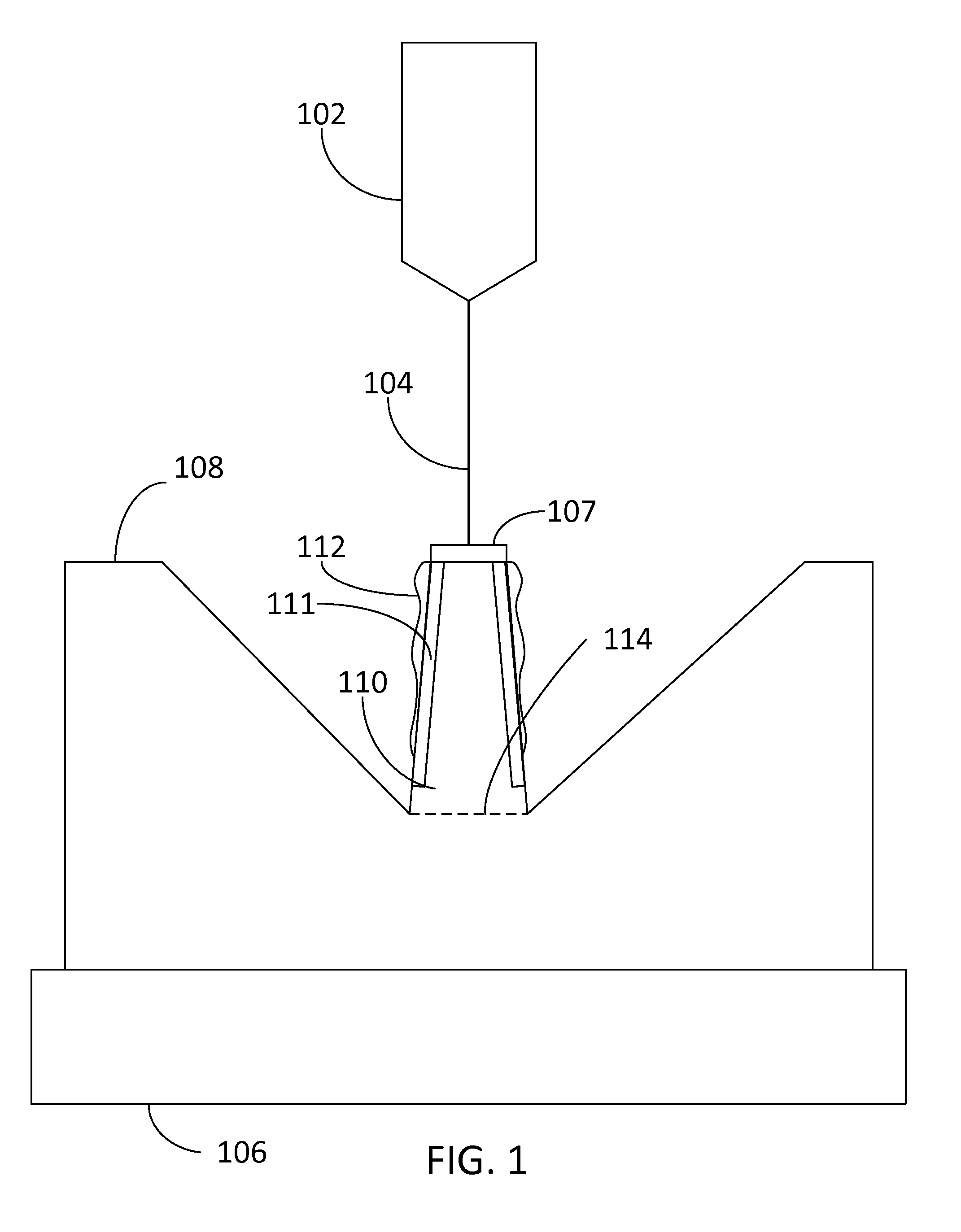
[0024]In accordance with some embodiments, a lamella suitable for S / TEM analysis is prepared using a focused ion beam or other method. After optional observation on S / TEM, material is deposited onto the thin lamella to form a thicker structure with the lamella embedded. The thicker structure is then milled to form a needle-like structure for atom probe microscopy. Thus, following this general sequence, a region of interest extracted from a bulk sample can be optimized for S / TEM and then separately optimized for the APM analysis. The embedded lamella sample structure also shows improved field evaporation characteristics compared to the traditional cone- or needle shaped structure having the region of interest and surrounding original matrix material largely intact relative to their positions in the bulk substrate. The improved data from the two sources can be more easily correlated thus improving the accuracy of the three-dimensional reconstructed microstructure and composition of th...


PUM

PropertyMeasurementUnit
thicknessaaaaaaaaaa
thicknessaaaaaaaaaa
thickaaaaaaaaaa

Abstract

A method of forming a sample and performing correlative S/TEM and APM analysis is provided wherein a sample containing a region of interest is cut from a bulk of sample material and formed into an ultra-thin lamella. The lamella is then analyzed with an S/TEM to form an image. The lamella sample and mount may then go through a cleaning process to remove any contamination. The lamella containing the ROI is then embedded within a selected material and is formed into a needle-shaped sample. The needle-shaped sample is then analyzed with the APM and the resulting data is merged and correlated with the S/TEM data.

Description

[0001]This application claims priority from U.S. Provisional App. 61 / 948,516, filed Mar. 5, 2014, which is hereby incorporated by reference.TECHNICAL FIELD OF THE INVENTION[0002]The present invention relates to a process of forming a sample that can be used for transmission electron microscopy and atom probe microscopy.BACKGROUND OF THE INVENTION[0003]Tomography is a rapidly advancing imaging technology with broad applications in such varied fields such as, for example, medicine, dentistry, biology, environmental, toxicology, mineralogy, and electronics. Tomography is the process of forming a 3-D image of a sample using various tools, such as, an x-ray system, a transmission electron microscope (TEM), scanning transmission electron microscope (STEM), and / or atom probe microscopy (APM) to obtain various types of information such as, for example, atomic structure and chemical analysis of the sample. A 3-D tomography dataset is typically obtained from a photon (e.g., optical or x-ray) ...

Claims


Application Information

Patent Timeline
Patent Type & Authority Applications(United States)
IPC IPC(8): G01Q30/02G01Q30/20
CPCG01Q30/20G01Q30/02H01J37/285H01J2237/31745G01N1/32G01N2001/282H01J2237/2802H01J2237/2852H01J2237/31749Y10T428/2933Y10T428/2958G01N1/00
Inventor ALVIS, ROGER
Owner FEI CO
Why Eureka
Try Eureka