Biogas process with nutrient recovery

a biogas and nutrient recovery technology, applied in the field of integrated processes, can solve the problems of reducing the efficiency of its own production and biogas production, reducing the use of acetic acid by acetoclastic methanogens, and subsequent ph decline, so as to achieve the effect of enhancing the yield of biogas

Active Publication Date: 2015-10-01
DUCTOR
View PDF1 Cites 11 Cited by
  • Summary
  • Abstract
  • Description
  • Claims
  • Application Information

AI Technical Summary

Benefits of technology

[0045]Optionally, gas produced in the first reactor is directed to the second reactor to enhance biogas yield.

Problems solved by technology

This leads to a decreased use of acetic acid by acetoclastic methanogens, and a subsequent pH decline caused by the accumulation of VFA.
Therefore, excess ammonia affects the anaerobic digestion process on many levels, decreasing both the efficiency of its own production as well as biogas production.
In biogas production, a high C / N ratio i.e. lack of nitrogen, leads to the inefficient utilization of carbon due to a lowered amount of microbial biomass, whereas a low C / N ratio, i.e. a surplus of nitrogen, can cause ammonia inhibition of methanogenesis.
However, for example, in the biogasification of nitrogen rich animal slaughter by-products, an increase of COD through co-digestion with carbon rich feedstock did not enhance methane production from the nitrogen rich feedstock (Resch et al.
The '351 patent process, however, limits its scope to nitrogen rich feedstock materials.
Ammonia is either lost to the atmosphere or recovered as such for hydrogen production, but not recovered in a form suitable for fertilizer use.
In addition, the conditions used, a mildly alkaline pH of 8-8.5 and a temperature of 55-65° C. do not favor volatilization of ammonia.
No elevated pH is used during stripping, which may cause inefficient stripping of ammonia and lead to ammonia inhibition during AD.
The described process is time-consuming and will only remove ammonia to some extent.
The downside of this method is that VFA are also washed out of the reactor along with ammonia, reducing the biogas yield.
The process does not characterize the microbial community performing conversion of organic nitrogen to inorganic nitrogen, and does not utilize nitrogen status control C / N ratio for providing optimal conditions for AD.

Method used


Image

  • Biogas process with nutrient recovery
  • Biogas process with nutrient recovery
  • Biogas process with nutrient recovery

Examples


example 1

Preammonification of Acidification-Inducing Feedstock Materials

[0137]The results of an experiment employing food waste (FW), porcine and bovine slaughter by-product (PB) and broiler chicken slaughter by-product (BC) are shown by TABLE 2. Food waste has a C / N molar ratio of approximately 14. It is nitrogen rich, but yet contains enough fermentable carbonaceous compounds to induce acidification and inhibit ammonification when used as a sole feedstock. Animal slaughter by-products have a C / N molar ratio below 10 and contain little carbohydrate. The results show that preammonification of a nitrogen rich material and ensuing ammonification of food waste produces highly improved yields, compared to digestion of food waste as a sole feedstock or in co-digestion with a nitrogen-rich material. Co-digestion gives a less than 20% yield when a PB 40%-FW 60% mix is used. However, when preammonification is applied, as little as 20% of PB is required for a >50% yield. The differences between feeds...

example 2

Modeling Nitrogen Content within the Biogasification Reactor

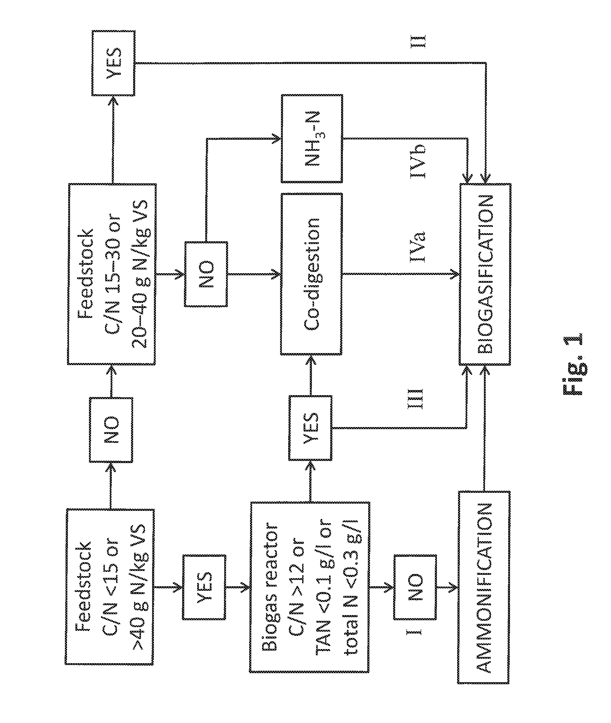
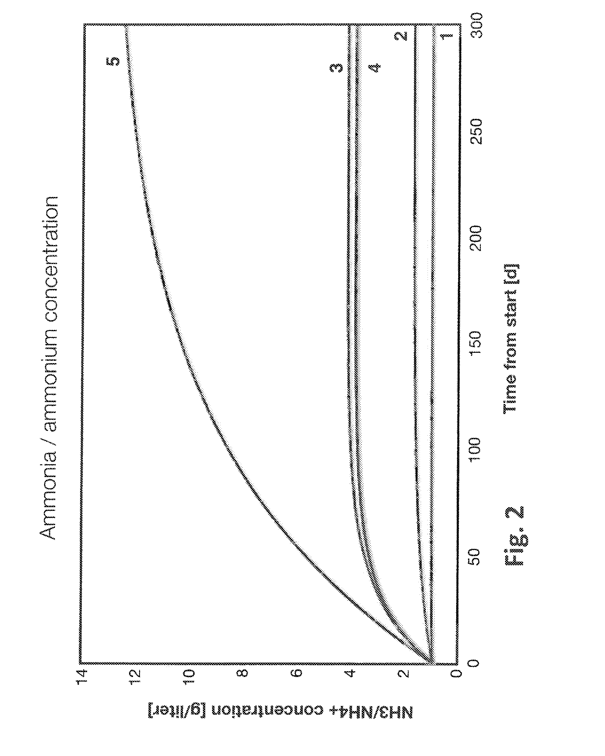
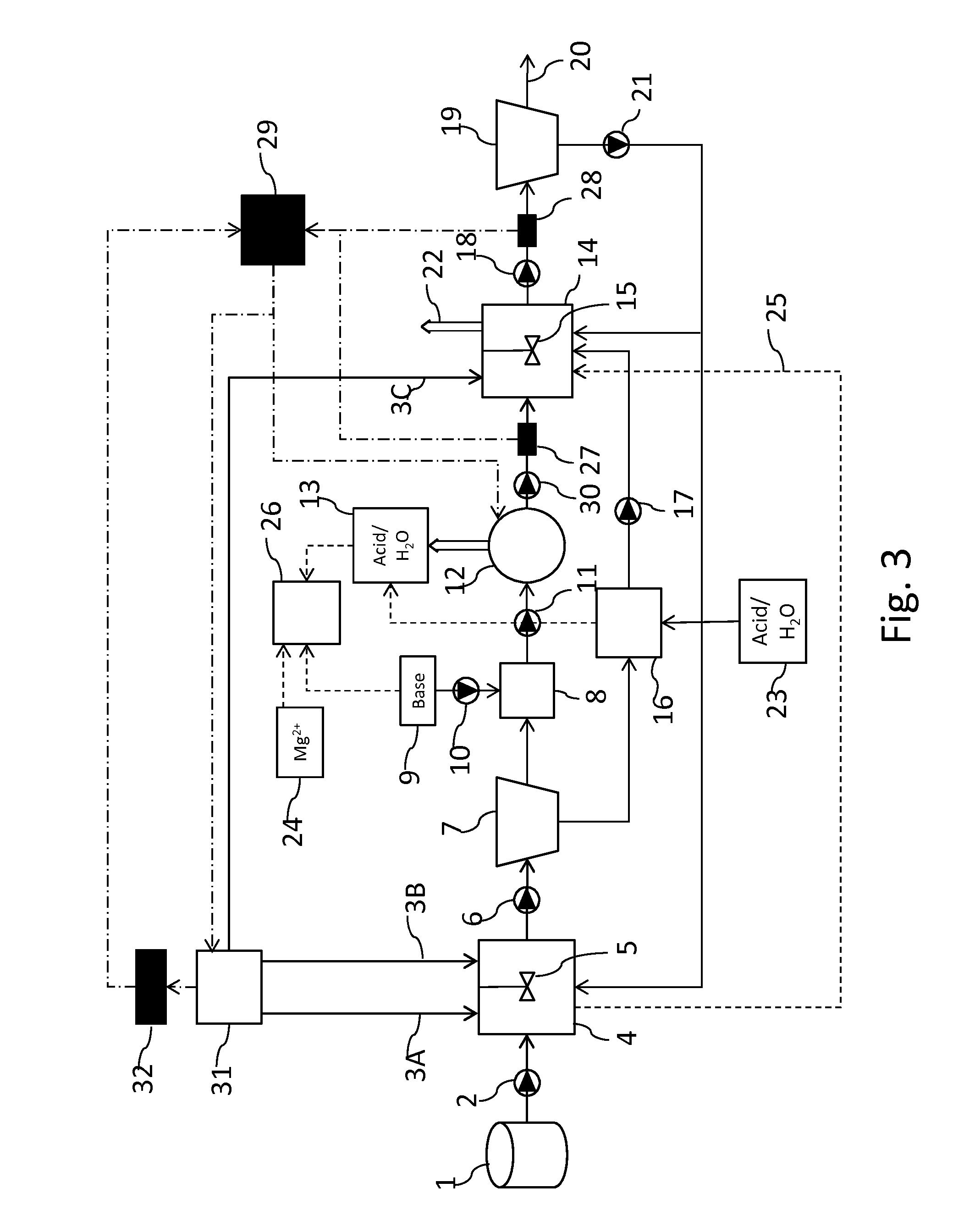
[0138]In the system of the present invention, feedstock may be sorted based on composition and selectively subjected to nitrogen removal to maintain the nitrogen concentration of a biogasification digester on an optimal level. A computational model was created for modeling the nitrogen concentration of a biogasification reactor of a biogas plant that separates carbon rich and nitrogen rich feedstocks and removes excess nitrogen either by (1) ammonification and subsequent stripping of the nitrogen rich feedstock before biogasification or (2) stripping reject water after biogasification.

[0139]The computational model calculates the nitrogen concentration of the biogasification reactor iteratively based on a set of parameters. For both feedstocks, it uses the following parameters: (1) total elemental nitrogen concentration, (2) total solids ratio, (3) volatile solids ratio and (4) proportion of total feedstock. Additionally, it...

example 3

Nitrogen Removal by Air Stripping

[0147]Ammonia removal by air stripping is dependent on pH level and temperature. Increasing the pH is used for shifting the ammonium / ammonia equilibrium towards the free ammonia form which is easily volatilized. Ammonium ions (NH4+) exist in equilibrium with ammonia (NH3) according to following reaction:

NH3+H2ONH4++OH−

[0148]Elevated temperature and aeration will increase the volatilization further and formed gaseous ammonia can be absorbed in neutral or acidic solution. In this example, an air stripper-acid scrubber column system was used for removal and recovery of ammonia.

[0149]Following the process setup described herein (see the section above in the Detailed Description entitled, “Process Setup” concerning FIG. 3), ammonified and centrifuged chicken litter broth (27.4 liters) was pH adjusted to 10.04 by adding NaOH solution (50%) from container 9. Then pH adjusted chicken litter broth was fed to ammonia removal unit by feed pump. The ammonia remo...


PUM

PropertyMeasurementUnit
molar ratioaaaaaaaaaa

Abstract

The invention is a method of two-phase anaerobic digestion where monitoring and adjusting the nitrogen status (carbon to nitrogen molar ratio, i.e. C/N molar ratio or total or ammoniacal nitrogen content) enables maintaining optimum conditions during the process. The method improves the use of a variety of feedstock materials or facilitates monodigestion of one feedstock. Especially the introduction of nitrogen rich feedstock materials in the process is amended. A community of hydrolyzing and acidogenic microorganisms in the first phase digester performs ammonification i.e. release of organic nitrogen as ammonia. Nitrogen and phosphorus are removed and recovered from the digestate which then undergoes biogasification in the second phase of the process. Reject water from biogasification can be recycled within the process.

Description

FIELD OF THE INVENTION[0001]This invention relates to an integrated process for optimizing the production of biogas by two-phase anaerobic digestion (AD) of feedstock, i.e., biomass or organic material. The integrated process of the invention particularly relates to determining the nitrogen status (carbon to nitrogen molar ratio, i.e. C / N molar ratio or total or ammoniacal nitrogen content) in the feedstock and at various steps of the process. More particularly, the invention provides utilization of nitrogen status control for optimization of the AD process and for introducing a variety of different feedstock materials into the process. The method of the invention employs ammonifying microbes for nitrogen mineralization during the first phase of AD, and a nitrogen and phosphate removal and recovery step before starting the second phase of AD to produce biogas. In addition, the method of the invention facilitates recirculation of biogasification reject water into the process.BACKGROU...

Claims


Application Information

Patent Timeline
Patent Type & Authority Applications(United States)
IPC IPC(8): C12P5/02
CPCC12P5/023C12M21/04C12M23/58C12M41/30C12P23/00Y02E50/30C12M45/00
Inventor KETOLA, ARIKOSKENNIEMI, KERTTULAHTINEN, MINNANUMMELA, JARKKOVIROLAINEN, NINAVIRKAJARVI, IIKKA
Owner DUCTOR
Why Eureka
Try Eureka