Microdevices for separation of non-spherical particles and applications thereof

a technology of micro-devices and non-spherical particles, applied in the field of micro-devices for separation of non-spherical particles and applications thereof, can solve the problems of complicated separation process that is ideally designed, cumbersome bench-top equipment, and traditional process of separating these biological entities or bioparticles, and achieve the effect of rapid detection and analysis of water samples

Inactive Publication Date: 2015-12-17
NAT UNIV OF SINGAPORE
View PDF3 Cites 16 Cited by
  • Summary
  • Abstract
  • Description
  • Claims
  • Application Information

AI Technical Summary

Benefits of technology

[0059]Algae come in various shapes and sizes. These algae can contaminate water sources or cause harm to humans or...

Problems solved by technology

Traditional processes of separating these biological entities or bioparticles involve cumbersome bench-top equipment employing centrifugal techniques, filtering, culturing and isolating.
This dependence on the spherical nature of a bioparticle poses a great challenge for the separation of non-spherical bioparticles because the smallest dimension of non-spherical particles determines the cut-off size for the separation.
Biological entities such as rod-shaped bacteria and disc shaped red blood cells (RBCs), to name but a few, have a disproportionate length or width (with respect to a spherical entity) which complicates the separation process that is ideally designed for spherical particles, as the narrowest width has to be considered for the separat...

Method used


Image

  • Microdevices for separation of non-spherical particles and applications thereof
  • Microdevices for separation of non-spherical particles and applications thereof
  • Microdevices for separation of non-spherical particles and applications thereof

Examples


Embodiment Construction

Having Regard to RBC Monitoring

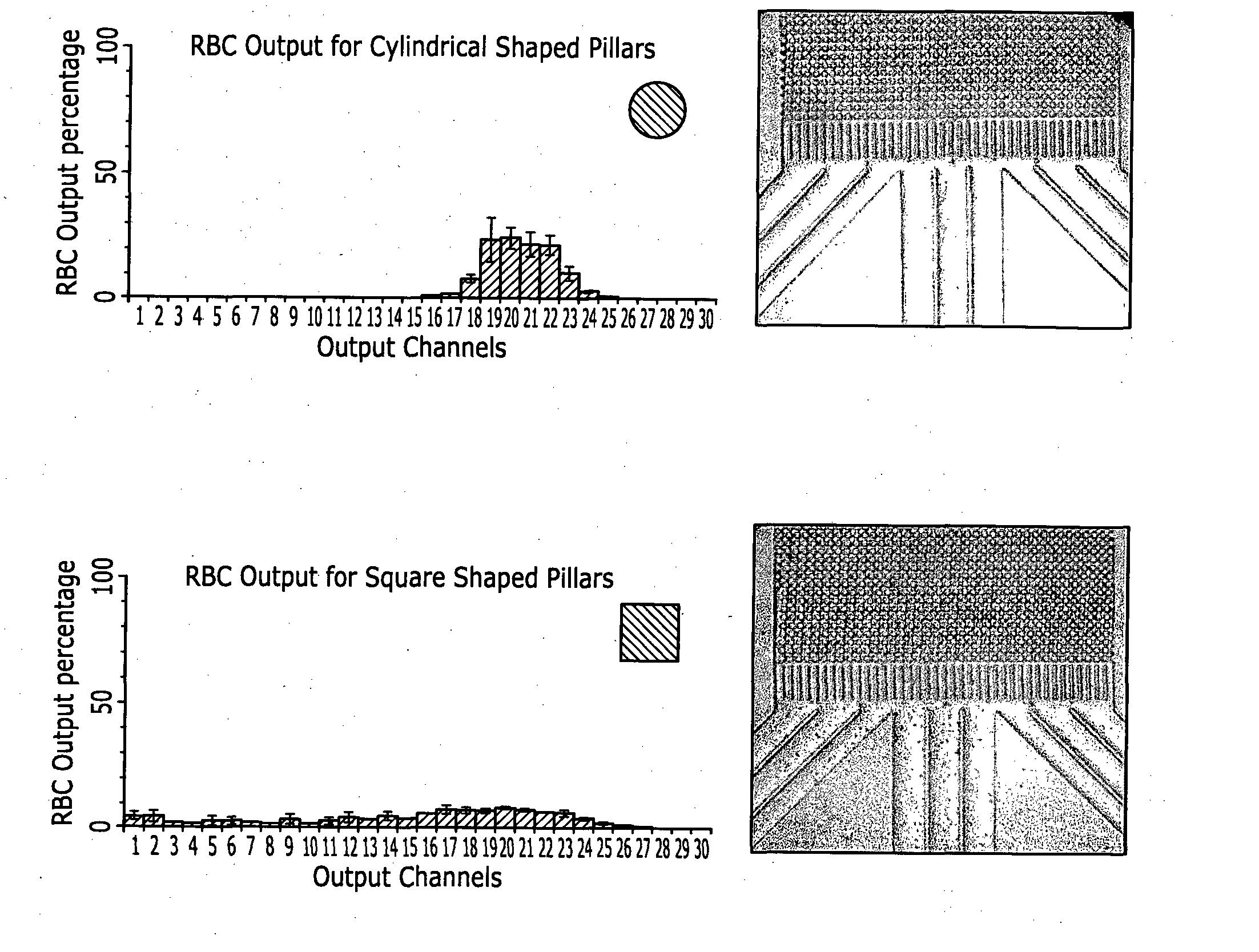
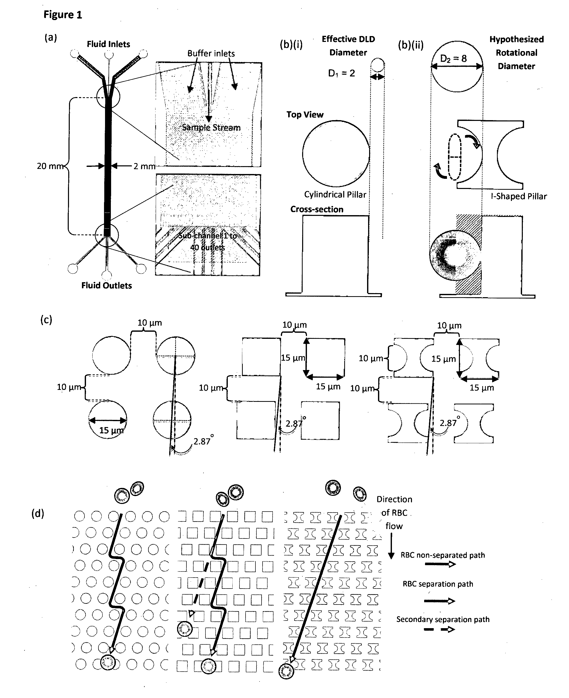
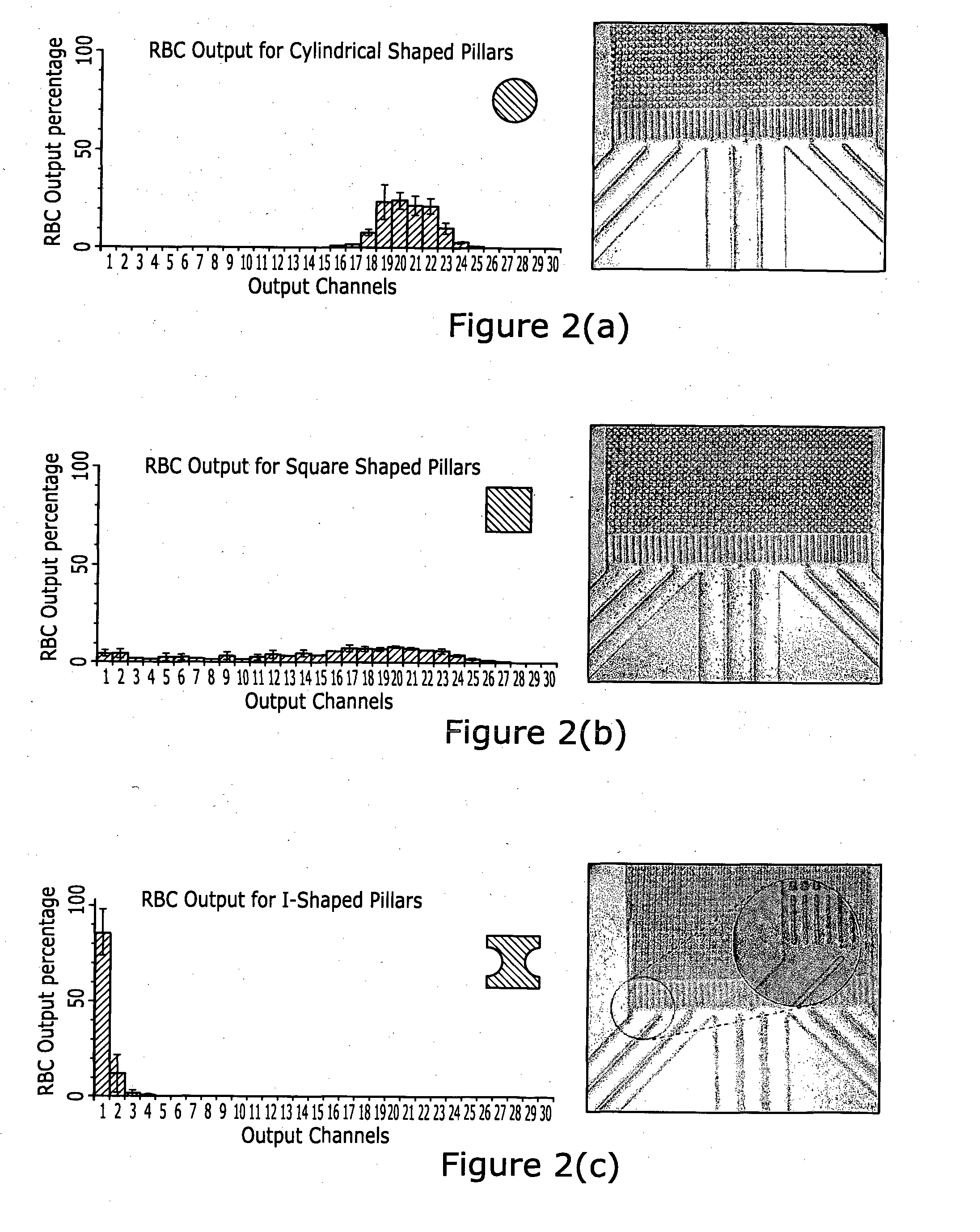
[0090]Device Fabrication The silicon microfluidic device was fabricated on a silicon wafer using standard lithographic techniques. A SUSS MA8 lithography machine was used to transfer the device design in FIG. 1(a) from a glass mask to a positive photo resist (AZ5214E) coated on the silicon surface. The wafer was placed in an Oxford 180 deep reactive ion etching machine to plasma etch the channels for the device. Piranha solution was used to remove any remaining photoresist on the wafer surface. A thin sheet of poly-dimethylsiloxane (PDMS) was fabricated and the inlet and outlet holes were punched before the PDMS was bonded over the silicon device using oxygen plasma. The device design shown in FIG. 1(a) comprises three inlet channels, a DLD main channel of 2 cm long and three outlet channels divided into 40 sub-channels for characterization of device separation efficiency. There are a total of three DLD designs as shown in FIG. 1(c), namely circle / cyli...


PUM

PropertyMeasurementUnit
Shapeaaaaaaaaaa

Abstract

The invention concerns at least one pillar in, or for use in, a microfluidic device wherein said pillar comprises, in cross-section, at least one particle abutment surface and an adjacent space that indents said pillar, or an adjacent groove that indents said pillar, to accommodate said particle; a plurality of such pillars arranged in an array; a method for separating particles in a fluid using said pillar, array or said device; and a diagnostic method involving the separation of particles from a fluid using said pillar, array or said device.

Description

[0001]The invention relates to at least one pillar in, or for use in, a microfluidic device said pillar comprising in cross-section at least one particle abutment surface and an adjacent space that indents said pillar, or an adjacent groove, to accommodate said particle; a plurality of such pillars arranged in an array; a method for separating non-spherical particles in a fluid using said pillar, array or said device; and a diagnostic method involving the separation of selected cells from a fluid using said pillar, array or said device.BACKGROUND OF INVENTION[0002]The capacity to isolate various biological entities such as pathogens and blood components enables the diagnosis and detection of diseases, infections and biological threats. Traditional processes of separating these biological entities or bioparticles involve cumbersome bench-top equipment employing centrifugal techniques, filtering, culturing and isolating. Advances in micro-machining have resulted in the development of ...

Claims


Application Information

Patent Timeline
IPC IPC(8): G01N1/40B01D21/00B01L3/00
CPCG01N1/4077B01L3/5027G01N2001/4083B01D21/00B01L2200/10B01L3/502761G01N15/1484B01L3/502753B01L2300/0816B01L2400/086
Inventor ZHANG, YONGRANJAN, SHASHIKWEK, ZEMING KERWIN
Owner NAT UNIV OF SINGAPORE
Why Eureka
Try Eureka