
Coating for intraluminal expandable catheter providing contact transfer of drug micro-reservoirs

a technology of expandable catheters and micro-reservoirs, which is applied in the direction of catheters, drug compositions, biocides, etc., can solve the problems of endothelial disruption, vessel tunica media dissection, and vessel injury to the vessel

Active Publication Date: 2016-01-21
M A MED ALLIANCE
View PDF22 Cites 8 Cited by
  • Summary
  • Abstract
  • Description
  • Claims
  • Application Information

AI Technical Summary

Benefits of technology

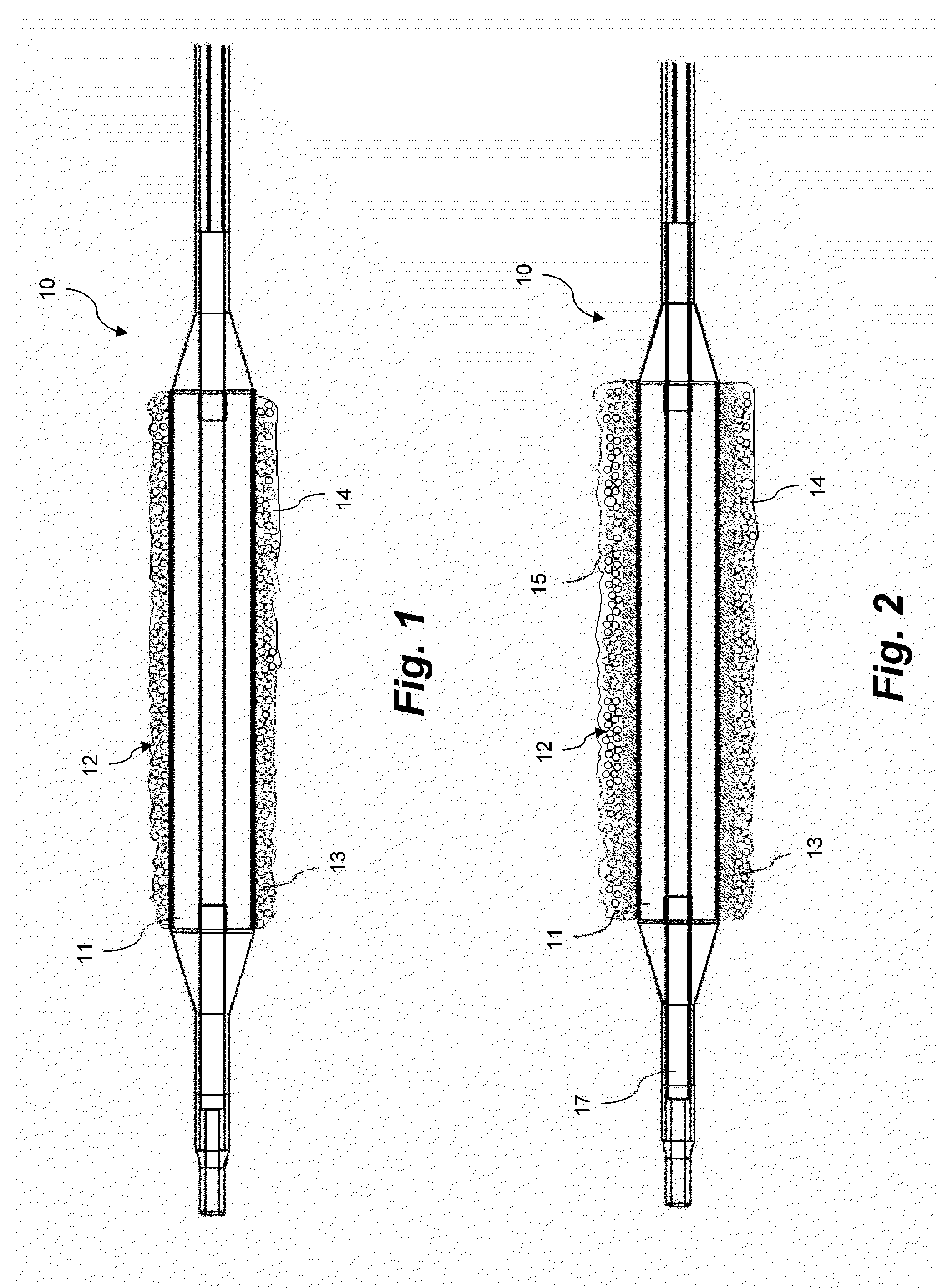
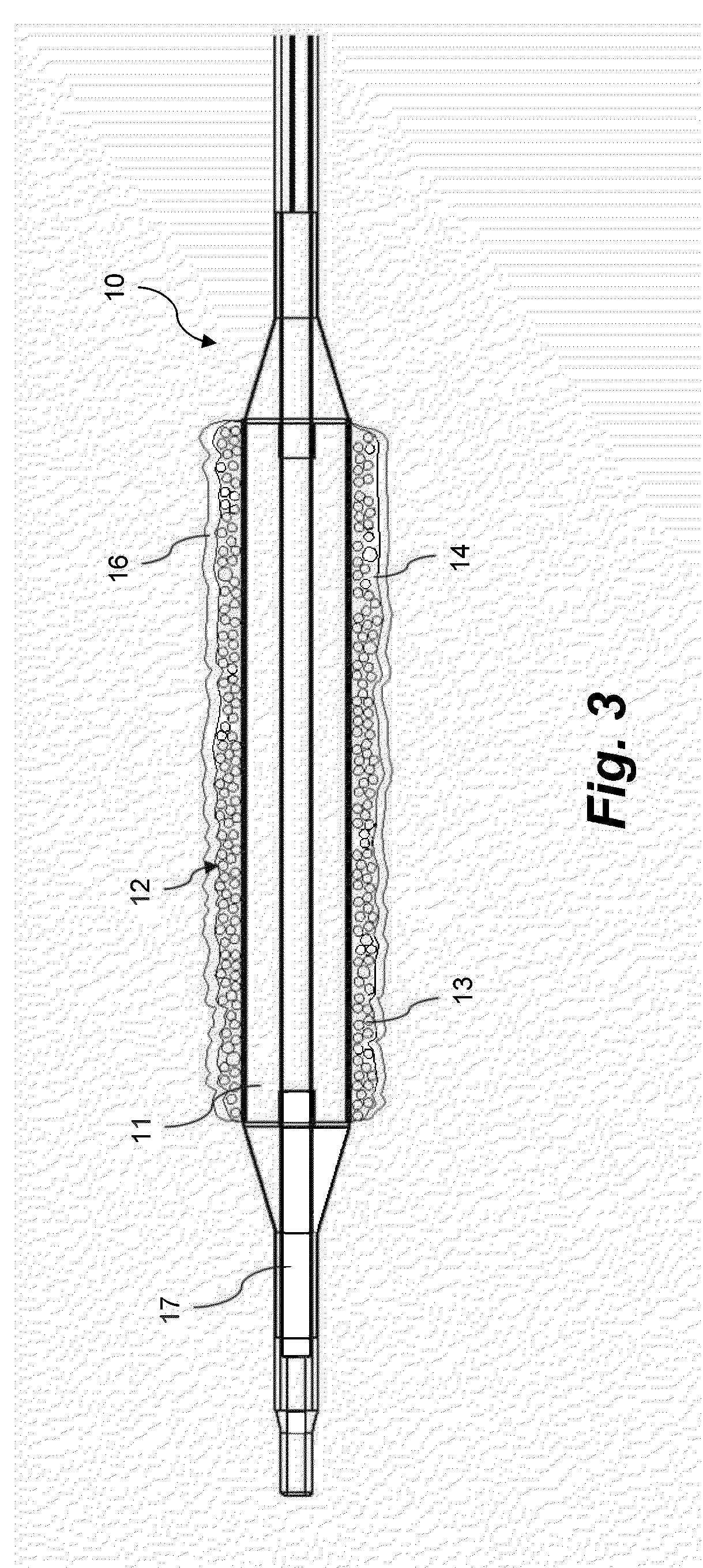
This patent describes a coating for the expandable portion of a catheter. The coating includes a hydrophobic matrix and a dispersed phase with micro-reservoirs containing a first active agent and a biodegradable or bioerodable polymer. The coating can be applied to the expandable portion of the catheter and is designed to release from the catheter at the treatment site. The coating can help deliver the active agent to the treatment site and can be easily applied and removed. This technology can improve the efficacy and accuracy of treatment while minimizing the risk of complications.

Problems solved by technology

The physical dilatation results in injury to the vessel, including endothelial disruption, fragmentation of the inner elastic lamina, and dissection of the vessel tunica media.
The restenosis effectively reverses the dilatation treatment and potentially creates a critical threat to the patient.
Although balloon angioplasty provides a critical increase in blood flow in diseased vessels, restenosis is inherent due to the extent of associated mechanical injury.
In practice, drug delivery to the tissues of the vessel wall by drug coated balloons as described in the art is limited by the short period of time during which the balloon may be placed in contact with the vessel.
Many of the drug coated balloons described in the prior art use high initial levels of active agent and multiple treatments to create a high initial concentration, but then the concentration rapidly falls off.
This is undesirable because most of the active agent on the device is lost as possible embolic particulate into the bloodstream, or by diffusion away from the treatment site.
However, such coatings do not provide significant resistance to wash off from blood either during maneuvering of the balloon to the treatment site or after transfer of the drug coating to the vessel surface.

Method used


Image

  • Coating for intraluminal expandable catheter providing contact transfer of drug micro-reservoirs
  • Coating for intraluminal expandable catheter providing contact transfer of drug micro-reservoirs
  • Coating for intraluminal expandable catheter providing contact transfer of drug micro-reservoirs

Examples


example 1

[0057]Drug Containing Micro-Reservoirs (Microspheres) spheres) fabricated by coacervation of polylactic-co-glycolic acid copolymer incorporating sirolimus (rapamycin) were obtained.

[0058]Microsphere sample 1: 50% DL-lactide / 50% glycolide copolymer, average diameter 3.1 μm, SD 0.44 μm, 39% rapamycin by weight

[0059]Microsphere sample 2: 75% DL-lactide / 25% glycolide copolymer, average diameter 3.2 μm, SD 0.76 μm, 40% rapamycin by weight

[0060]Microsphere sample 3: 50% DL-lactide / 50% glycolide copolymer, average diameter 2.7 μm, SD 0.8 μm, 45% rapamycin by weight

[0061]Microsphere sample 4: 75% DL-lactide / 25% glycolide copolymer, average diameter 3.3 μm, SD 1.2 μm, 46% rapamycin by weight

[0062]Microsphere sample 5: 75% DL-lactide / 25% glycolide copolymer, average diameter 4.1 μm, SD 0.61 μm, 25% rapamycin by weight

[0063]Microsphere sample 6: 75% DL-lactide / 25% glycolide copolymer, average diameter 3.78 μm, SD 0.44 μm, 28.8% rapamycin by weight

[0064]Microsphere sample 7: 75% DL-lactide / 25% ...

example 2

Sustained Drug Release from Micro-Reservoirs under Physiological Conditions

[0067]Micro-reservoirs from Example 1 were tested for sustained release of drug. Micro-reservoir samples of 2 to 5 mg weight were placed in 1.6 ml Eppendorf tubes with 1.2 ml of phosphate buffered saline (PBS) to simulate a physiological environment. After an initial wash to remove any drug not incorporated in the micro-reservoirs, the tubes were incubated at 37° C. with gentle mixing at 250 rpm. The PBS was sampled at time intervals and the released drug quantitated by reverse phase HPLC using a C18 column.

[0068]Micro-reservoirs were assayed for drug elution over 5 hours. The resultant drug release was fit to the Korsmeyer-Peppas kinetic equation for drug release from a polymer with dispersed drug. The results of the Korsmeyer-Peppas model are listed in Table 1.

TABLE 1Korsmeyer-Peppas Modeling of 5 Hour Drug ReleaseMicrosphereMicrosphereMicrosphereMicrosphereQ = a * x{circumflex over ( )}b1234R (correlation0...

example 3

Formulations of Micro-Reservoirs in Coating Formulation of Cholesterol and Fatty Acid with PEG-Lipid

[0076]A coating formulation was prepared with 107 mg of stearic acid, 105 mg of cholesterol, and 50 mg of DPPE-mPEG350 mixed with 14 mL of heptane and heated to 60° C. such that a clear solution was obtained. The solution was then vortex mixed for 30 seconds and allowed to cool. Next, 200 mg of sirolimus loaded microspheres of sample #6 was added, and the formulation was placed in an ultrasonic bath for 4 minutes to disperse and suspend the microspheres. [Formulation 1023E]

[0077]A coating formulation was prepared with 58 mg of erucic acid, 43 mg of DC-Cholesterol, and 6.25 mg of DOPE-mPEG350 mixed with 7 mL of heptane and heated to 60° C. such that a clear solution was obtained. The solution was then vortex mixed for 30 seconds and allowed to cool. Next, 100 mg of sirolimus loaded microspheres of sample #8 was added, and the formulation was placed in an ultrasonic bath for 5 minutes t...


PUM

PropertyMeasurementUnit
Fractionaaaaaaaaaa
Fractionaaaaaaaaaa
Fractionaaaaaaaaaa

Abstract

A coating for an expandable portion of a catheter comprising a hydrophobic matrix and a dispersed phase is disclosed. The dispersed phase comprises a plurality of micro-reservoirs dispersed in the hydrophobic matrix, wherein the plurality of micro-reservoirs comprises a first active agent and a first biodegradable or bioerodable polymer. A coating formulation and a method for forming the coating are also disclosed. A catheter comprising the coating on the expandable portion and a method for treating a condition are also provided.

Description

BACKGROUND OF THE INVENTION[0001]1. Field of the Invention[0002]This disclosure is related to the field of drug delivery via expandable catheters.[0003]2. Description of the Related Art[0004]Balloon angioplasty is an established method for the treatment of vascular disease by physically dilating an area of atherosclerosis, stenosis or reduction in luminal diameter in a diseased blood vessel. Angioplasty is typically performed with a catheter which may be advanced within the circulatory system to the diseased area. The catheter has a balloon at the distal end that is inflated to dilatate and expand the area of stenosis. In many cases, such as in the coronary arteries, a stent is also expanded on the exterior of the balloon. The stent is left in place after deflation and removal of the balloon to maintain the patency of the expanded lumen.[0005]In order to achieve the physical enlargement of the vessel, large forces are exerted upon the tissues of the vessel during high pressure ballo...

Claims


Application Information

Patent Timeline
IPC IPC(8): A61L29/08A61K31/436A61L29/06A61L29/12A61L29/16
CPCA61L29/085A61K31/436A61L29/126A61L2420/06A61L29/16A61L2300/216A61L29/06A61L29/08A61L29/12A61L29/14A61L2300/422A61L2300/416A61L2300/602A61L2420/02A61L2420/08C08L71/02A61L2420/04A61P9/10A61P9/14A61L29/148A61M2025/1031A61M2025/105A61K31/337A61P35/00A61L2300/604A61L2300/608A61M25/10A61M25/1027
Inventor AHLERING, MICHAEL THOMASYAMAMOTO, RONALD KENICHIELICKER, ROBERT JOHNNGUYEN, TIEN THUYSHULZE, JOHN EDWINZOETHOUT, JELLE JURJEN
Owner M A MED ALLIANCE
Learn More