
Flexible transparent electrode and method for manufacturing same

a flexible, electrode technology, applied in the direction of dielectric characteristics, metal/alloy conductors, conductive layers on insulating supports, etc., can solve the problems of increased electrical conductivity, decreased optical transparency, high manufacturing price, etc., to reduce manufacturing costs, enhance transparency, and simplify the effect of processes

Inactive Publication Date: 2016-01-28
IND ACADEMIC CORP FOUND YONSEI UNIV
View PDF3 Cites 13 Cited by
  • Summary
  • Abstract
  • Description
  • Claims
  • Application Information

AI Technical Summary

Benefits of technology

The present invention aims to provide a flexible and transparent electrode that can apply DC voltage without being affected by an electric field. The electro contains a mesh pattern formed by droplets that are charged equally and attached to a substrate when voltage is applied. The invention uses an electrohydrodynamic jet printing device which makes it easy to manufacture the electro. The technical effects of this invention include the ability to produce a flexible and transparent electrode with a patterned mesh structure that can apply DC voltage without being affected by an electric field.

Problems solved by technology

However, such characteristics are applied only when ITO is a thin film, and if ITO exceeds a predetermined thickness, electrical conductivity increases but optical transparency decreases.
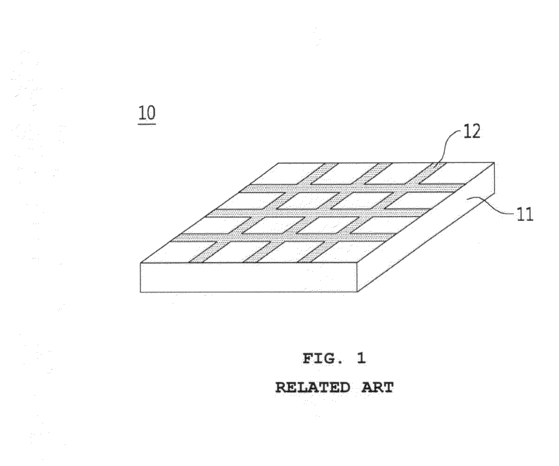
However, the transparent electrode using indium tin oxide according to the prior art has a problem in that manufacturing price is high because material prices of indium tin oxide are high due to limited resources of indium.
Furthermore, indium tin oxide has another problem in that it is fragile because it is weak to an external force, such as flexure.
Additionally, a general process to manufacture an indium tin oxide thin film is very complicated because it requires a high vacuum condition.
However, it is hard for such materials to satisfy electrical conductivity as well as transparency.
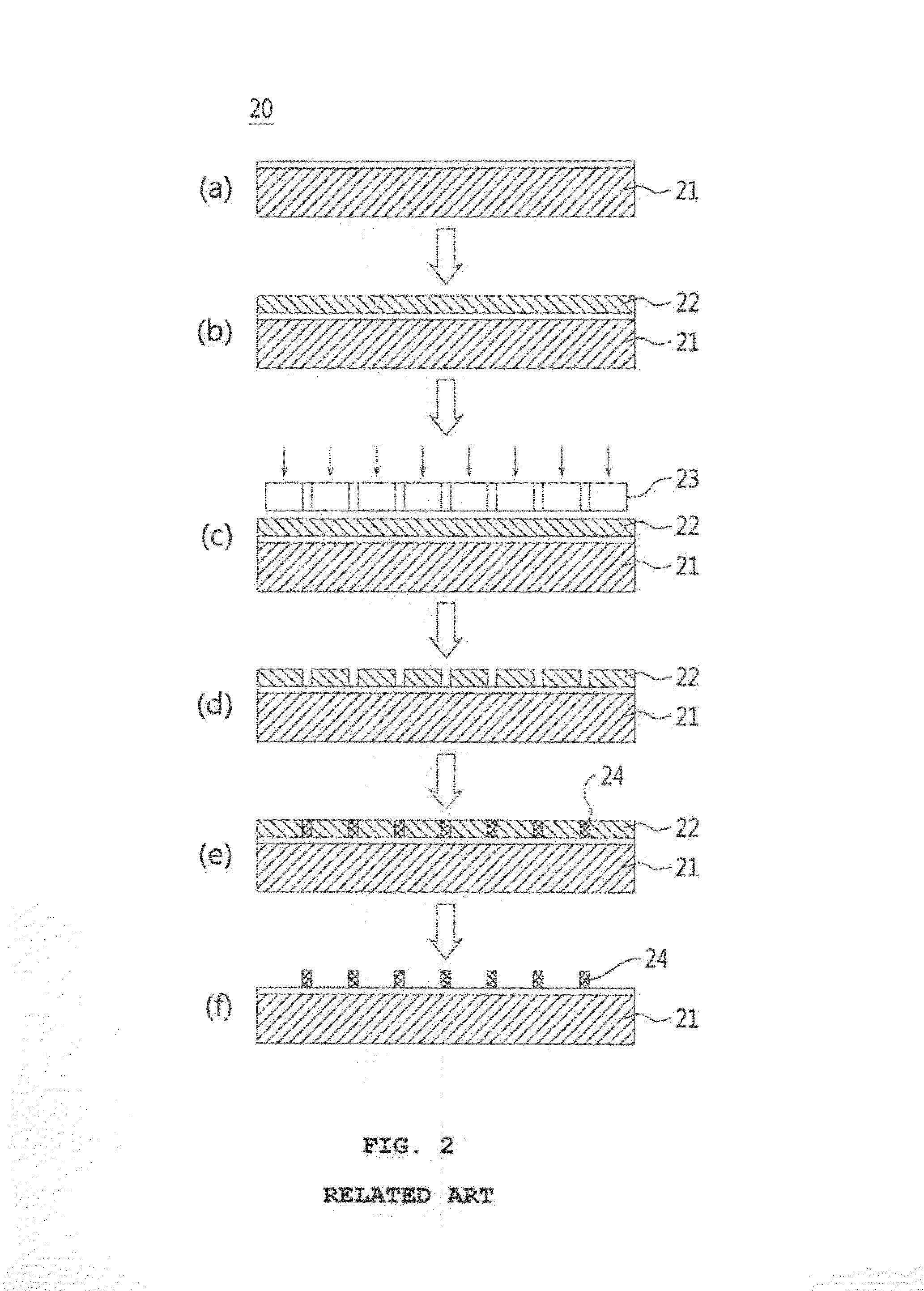
Lithography is unfavorable in an aspect of environmental pollution because it uses special chemical substances which are dangerous and are complicated in process phases.
The inkjet method is a direct writing method capable of patterning a mesh structure but is disadvantageous in manufacturing the transparent electrode due to a thick linewidth.
However, the conventional inkjet method cannot be applied to the transparent electrode manufacturing method because it cannot embody the linewidth under 50 μm.
However, when a nozzle of a fine size is used, there are several limitations in that nozzle clogging frequently occurs at a nozzle outlet and in that it is difficult to attach the sprayed droplets onto a designated position of the surface of the substrate owing to the Brownian movement in the air.
The producing method proposed in the thesis can partially solve the problems of the prior arts because it can form high-solution patterns using inkjet technology, but has a new problem in that it requires complicated processes in production.
In addition, the producing method proposed in the thesis has another problem in that time required for production is long and manufacturing costs are increased because the method needs pre-treatment processes of multiple stages for inkjet printing.
Such an electrohydrodynamic jet printing technology may have a positive influence on refinement of the linewidth, but has several problems in that it has a limitation in installation and management of ground electrodes and in that it is difficult to form patterns stably because electrical influences are varied according to materials and thickness of the substrate 33.
Therefore, also the transparent electrode manufacturing method using the electrohydrodynamic jet printing technology according to the prior art cannot obtain a stable pattern.

Method used


Image

  • Flexible transparent electrode and method for manufacturing same
  • Flexible transparent electrode and method for manufacturing same
  • Flexible transparent electrode and method for manufacturing same

Examples


Embodiment Construction

[0068]Hereinafter, reference will be now made in detail to the preferred embodiments of the present invention with reference to the attached drawings, but the scope of the present invention is not limited by the attached drawings and embodiments. In addition, in the description of the present invention, when it is judged that detailed descriptions of known functions or structures related with the present invention may make the essential points vague, the detailed descriptions of the known functions or structures will be omitted.

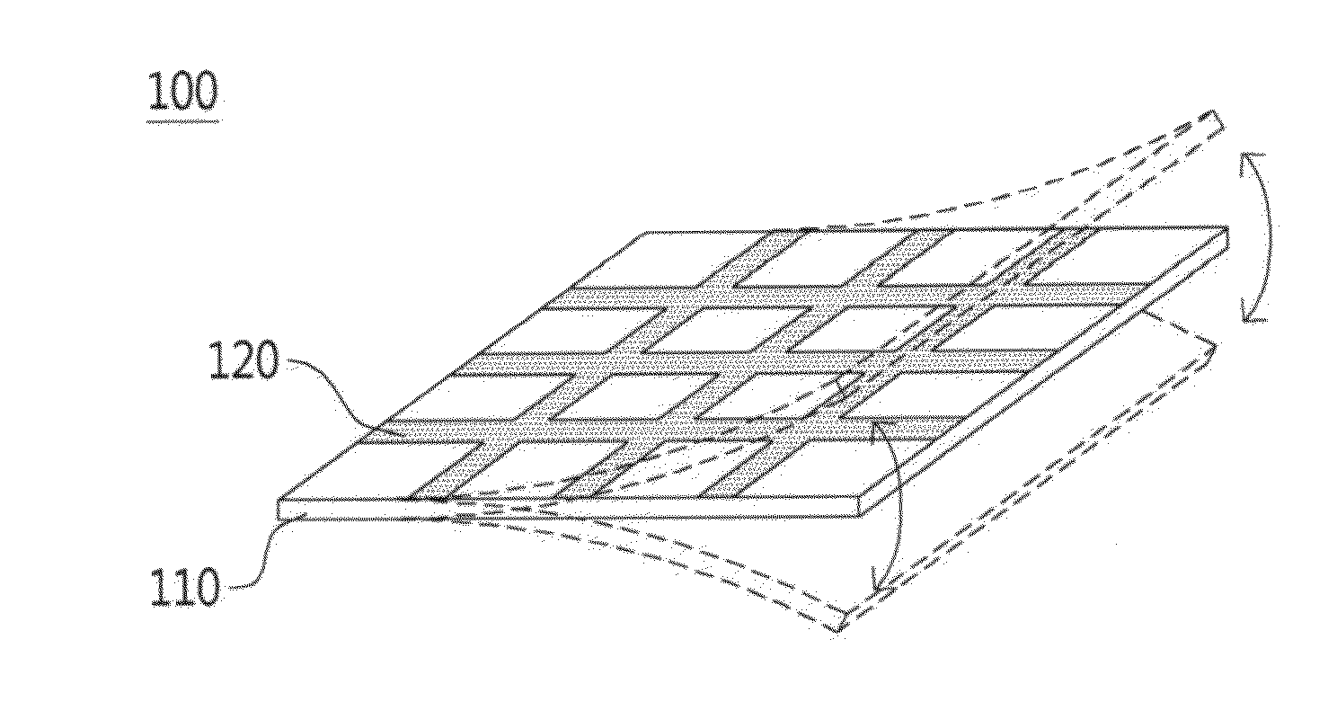
[0069]FIG. 6 is a perspective view of a transparent electrode according to the present invention.

[0070]Referring to FIG. 6, the transparent electrode 100 according to an embodiment of the present invention is flexible transparent electrode, and includes a substrate 110 made of a flexible and transparent material and a metal pattern 120 which is formed on the substrate 110 in a mesh form and has an electroconductive metal material.

[0071]In this instance, the m...


PUM

PropertyMeasurementUnit
distanceaaaaaaaaaa
temperatureaaaaaaaaaa
transmittanceaaaaaaaaaa

Abstract

A flexible transparent electrode and a method for manufacturing the same are provided. The flexible transparent electrode includes: a substrate made of a flexible and transparent material, and a metal pattern which is formed on the substrate in a mesh form and has an electroconductive metal material, wherein the metal pattern is formed by being patterned on an upper side of the substrate using an electrohydrodynamic jet printing method and being sintered, and the electrohydrodynamic jet printing method is a method of forming a metal pattern on the upper side of the substrate after applying AC voltage of a predetermined power to the substrate and an injection nozzle of an electrohydrodynamic jet printing device. The flexible transparent electrode and the method for manufacturing the same can manufacture transparent electrode of a flexible structure through more simplified processes and reduce manufacturing costs.

Description

BACKGROUND OF THE INVENTION[0001]1. Field of the Invention[0002]The present invention relates to a flexible transparent electrode and a method for manufacturing the same, and, more particularly, to a flexible transparent electrode and a method for manufacturing the same using electrohydrodynamic jet printing.[0003]2. Background Art[0004]Conventional transparent electrodes mainly use indium tin oxide (ITO). Indium tin oxide is a mixture of In2O3 and SnO2, and generally has 90% of In2O3 and 10% of SnO2. In general, Indium tin oxide is called “ITO”. ITO has transparency when it is manufactured into a thin film. Moreover, ITO has high electrical conductivity and optical transparency. However, such characteristics are applied only when ITO is a thin film, and if ITO exceeds a predetermined thickness, electrical conductivity increases but optical transparency decreases. The thin film of ITO may be generally deposited onto the surface by electron beam deposition, vapor deposition, or sputt...

Claims


Application Information

Patent Timeline
Patent Type & Authority Applications(United States)
IPC IPC(8): H05K1/02H05K1/03H05K1/09H05K3/00
CPCH05K1/028H05K3/0091H05K1/097H05K1/0313H05K1/0393H05K3/125H05K2201/0108H05K2201/09681H01B1/02H01B5/14H01B13/00
Inventor HWANG, JUNGHOPARK, JAEHONG
Owner IND ACADEMIC CORP FOUND YONSEI UNIV
Learn More