Carbon member, carbon member manufacturing method, redox flow battery and fuel cell

a technology of carbon member and manufacturing method, which is applied in the direction of cell components, sustainable manufacturing/processing, indirect fuel cells, etc., can solve the problems of battery member prone to delamination, difficult to achieve satisfactory conduction at the battery material interface, and unsatisfactory welding properties of adhesives, etc., to achieve excellent conductivity, superior flexural strength, and low resistance

Inactive Publication Date: 2016-03-03
SHOWA DENKO KK
View PDF0 Cites 10 Cited by
  • Summary
  • Abstract
  • Description
  • Claims
  • Application Information

AI Technical Summary

Benefits of technology

[0038]The carbon member of the present invention is obtained by welding, into a single integrated body: a first layer containing a first resin composition and a first carbonaceous material, a second layer disposed in contact with at least one main surface of the first layer and containing a second resin composition and a second carbonaceous material, and a third layer, which is disposed facing the first layer with the second layer interposed therebetween and is formed from a porous carbon material, and the resulting carbon member has low resistance in the thickness direction (penetration resistance), excellent conductivity and superior flexural strength.
[0039]Further, when the carbon member of

Problems solved by technology

In a conventional carbon member, when adjacent battery members are welded together with an adhesive, achieving satisfactory conduction at the battery material interface has proven difficult.
However, when adjacent battery members are welded together using a substance containing a conductive

Method used


Image

  • Carbon member, carbon member manufacturing method, redox flow battery and fuel cell
  • Carbon member, carbon member manufacturing method, redox flow battery and fuel cell
  • Carbon member, carbon member manufacturing method, redox flow battery and fuel cell

Examples


examples 1 to 29

, Reference Examples 1 and 2, Comparative Examples 1 to 10

[0148]Using resin compositions P01 to P15 shown in Table 1, carbonaceous materials C1 to C7 shown in Table 2, and porous carbon materials EL1 to EL8 shown in Table 3, the methods described below were used to manufacture and evaluate carbon members of Example 1 to Example 29, Reference Examples 1 and 2, and Comparative Example 1 to Comparative Example 10 shown in Table 4 to Table 10.

TABLE 1P01P02P03P04P05P06P07P08P09P10P11VS200A (homo PP) MFR = 0.5 (230° C.), 2.16 kgmass %95PMB60A (block PP) MFR = 63 (230° C.), 2.16 kgmass %95PL400A (homo PP) MFR = 2 (230° C.), 2.16 kgmass %95100PM801A (homo PP) MFR = 13 (230° C.), 2.16 kgmass %95PP2228 (PP-based copolymer) MFR = 30 (230° C.), 2.16 kgmass %100Q100F (PP-based copolymer) MFR = 0.6 (230° C.), 2.16 kgmass %90PM940M (random PP) MFR = 30 (230° C.), 2.16 kgmass %1007040PB0800M (polybutene-1) MFR = 820 (230° C.), 2.16 kgmass %100DP8510M (polybutene-1) MFR = 168 (230° C.), 2.16 kgmass ...

example 1

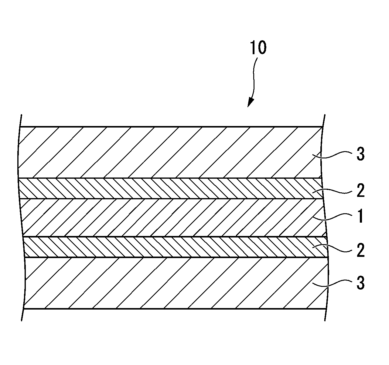
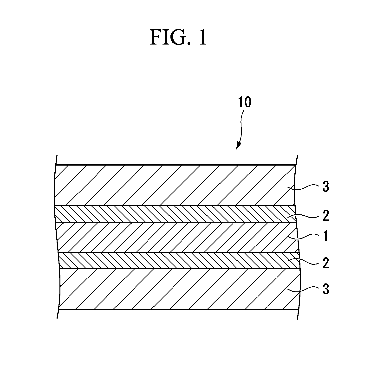
[0201]Using a unidirectional twin-screw extruder (KTX-30, manufactured by Kobe Steel, Ltd.), 100 parts by mass of the resin composition P01 and 600 parts by mass of the carbonaceous material C1 were compounded under an open-head state including a temperature setting of 210° C. and a rotational rate of 400 rpm, thus forming a mixture. Subsequently, the mixture was extrusion-molded at a temperature setting of 200° C. using a single screw sheet extruder, thereby forming a sheet-like first layer having a length of 200 mm, a width of 200 mm and a thickness of 1.5 mm (first molding step).

[0202]Further, 100 parts by mass of the resin composition P08, 300 parts by mass of the carbonaceous material C1 and 100 parts by mass of the carbonaceous material C4 were compounded to prepare a mixture and then extrusion molded in a similar manner to the first layer, thereby forming a sheet-like second layer having a length of 200 mm, a width of 200 mm and a thickness of 1.5 mm (second molding step). Th...

example 2

[0205]Using the same method as Example 1, a mixture for forming the first layer was produced, and by subsequently shaping and extruding the mixture through the die of a twin screw extruder, a sheet-like first layer having a length of 100 mm, a width of 100 mm and a thickness of 1.5 mm was molded.

[0206]Using the resin composition and the carbonaceous materials shown in Table 4, and in a similar manner to the first layer, a step of forming a mixture for the second layer and a step of molding the mixture into a sheet-like second layer with a length of 100 mm, a width of 100 mm and a thickness of 1.5 mm were performed in a continuous manner. Subsequently, the obtained sheet-like second layer was rolled to prepare a sheet-like second layer with a thickness of 0.1 mm.

[0207]With the exception of using the thus obtained sheet-like first layer and sheet-like second layer, the first layer, second layers and third layers were stacked in the same manner as Example 1 to obtain a carbon member of...


PUM

PropertyMeasurementUnit
Temperatureaaaaaaaaaa

Abstract

A carbon member for use as a battery member of a redox flow battery or a fuel cell, obtained by welding, into a single integrated body: a first layer including a first resin composition containing a polyolefin-based resin and having a melt flow rate of 0.01 to 10 g/10 min, and a first carbonaceous material; a second layer including a second resin composition containing a polyolefin-based resin, having a melt flow rate of 5 to 1,000 g/10 min that is greater than that of the first resin composition, and having a melting point that is 80° C. or higher, but is at least 10° C. lower than that of the first resin composition, and a second carbonaceous material; and a third layer, which is disposed facing the first layer with the second layer interposed therebetween, and is formed from a porous carbon material having a specified bulk density.

Description

BACKGROUND OF THE INVENTION[0001]1. Field of the Invention[0002]The present invention relates to a carbon member having a multilayer structure in which a carbon resin composition material layer and a porous carbon material layer are integrated into a single body, and a manufacturing method for the carbon member, and relates particularly to a carbon member that is suitable as a battery member for use in a battery such as a redox flow battery or a fuel cell, and a manufacturing method for the carbon member. Priority is claimed on Japanese Patent Application No. 2013-082949, filed Apr. 11, 2013, the content of which is incorporated herein by reference.[0003]2. Description of Related Art[0004]Conventionally, sintered carbon obtained by conducting sintering in a high-temperature process has been widely used as the material for carbon members used as battery members such as electrodes. By using sintered carbon, a high-performance carbon member having low electrical resistance and excellen...

Claims


Application Information

Patent Timeline
IPC IPC(8): H01M8/18H01M8/02
CPCH01M8/188H01M8/0297H01M4/96H01M8/1004H01M8/1023Y02E60/528H01M4/88Y02P70/56Y02E60/521H01M8/20H01M8/0213H01M8/0221H01M8/0228H01M8/0234H01M8/0239H01M8/0245Y02E60/50Y02P70/50
Inventor IINO, TADASHISUZUKI, SHUNYA
Owner SHOWA DENKO KK
Why Eureka
Try Eureka