Supercharge Your Innovation With Domain-Expert AI Agents!

Plasma processing apparatus

a processing apparatus and plasma technology, applied in the direction of transformer/inductance details, chemical vapor deposition coating, coating, etc., can solve the problems of reducing the production yield of semiconductor devices or display devices, wasting high frequency power, and degrading the operation and performance of heater power supplies, so as to achieve the effect of reducing an impedance function or a withstand voltage characteristic without reducing the function

Active Publication Date: 2016-05-05
TOKYO ELECTRON LTD
View PDF2 Cites 3 Cited by
  • Summary
  • Abstract
  • Description
  • Claims
  • Application Information

AI Technical Summary

Benefits of technology

The plasma processing apparatus described in this patent can adjust or optimize the resonance frequency of the processing vessel without reducing its impedance function or withstanding voltage against high frequency noise. It achieves this by using a multiple parallel resonance characteristic of a distributed constant line to block the high frequency noise introduced from outside the processing vessel.

Problems solved by technology

If the temperature control of the substrate is not properly performed, not only the uniformity of a surface reaction of the substrate but also the uniformity of process characteristics may not be achieved, so that a production yield of semiconductor devices or display devices is decreased.
When using this heater structure, however, a part of a high frequency power applied to the susceptor from a high frequency power supply may be easily introduced into a heater power feed line through the heating element as a noise.
If this high frequency noise reaches a heater power supply through the heater power feed line, operation and performance of the heater power supply is degraded.
Furthermore, if a high frequency current flows in the heater power feed line, the high frequency power may be wasted.

Method used


Image

  • Plasma processing apparatus
  • Plasma processing apparatus
  • Plasma processing apparatus

Examples


first exemplary embodiment

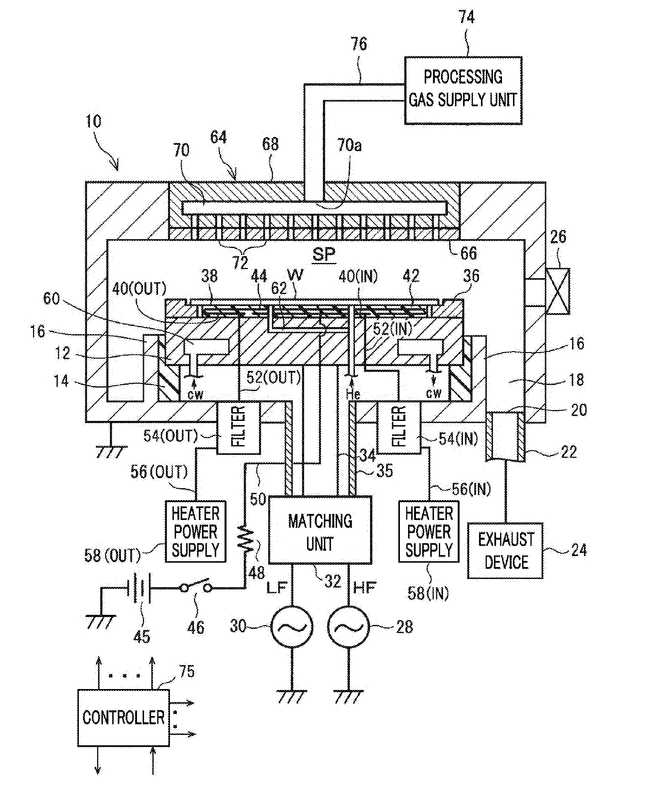
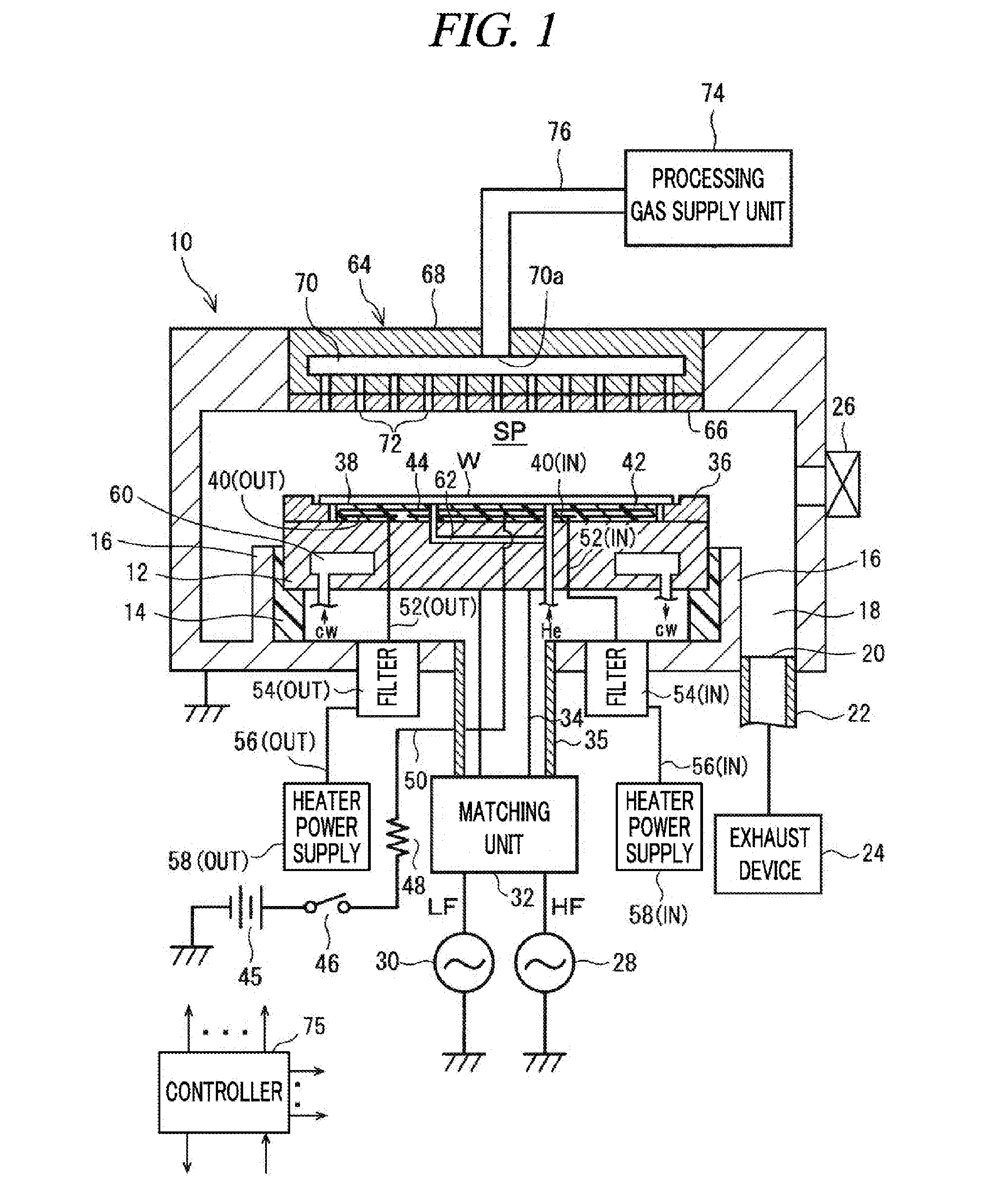
[0085]FIG. 4A, FIG. 4B and FIG. 5 illustrate a physical structure within the filter unit 54(IN) in accordance with a first example embodiment. The filter unit 54(IN) includes, as depicted in FIG. 4A and FIG. 4B, a cylindrical outer conductor 110 made of, but not limited to, aluminum, in which the solenoid coil 104(1) of the first filter 102(1) and the solenoid coil 104(2) of the second filter 102(2) are arranged coaxially. Further, the filter unit 54(IN) also includes a capacitor box 112 which is made of, but not limited to, aluminum and provided at the opposite side from the filter terminals T(1) and T(2). In the capacitor box 112, the capacitor 106(1) of the first filter 102(1) and the capacitor 106(2) of the second filter 102(2) (FIG. 2) are accommodated. The outer conductor 110 is screw-coupled to a conductive member of a ground potential, for example, the chamber 10.

[0086]Each of the solenoid coils 104(1) and 104(2) is formed of an air core coil. Further, each of the solenoid c...

second exemplary embodiment

[0135]In this second exemplary embodiment, as in the first exemplary embodiment, instead of providing the ring member between the solenoid coils 104(1) and 104(2) and the outer conductor 110 within the filter unit 54(IN), a physical characteristic of the solenoid coils 104(1) and 104(2), which determines C and / or L of the coaxial line, is set or adjusted independently for each of the multiple sections K1, K2, . . . . Thus, a characteristic impedance Zo=√(LC) is changed in each section without changing the gap of the coaxial line, so that a part or all of resonance frequencies of multiple parallel resonance are shifted.

[0136]More specifically, in the inter-winding structure, the solenoid coils 104(1) and 104(2) are divided to the multiple sections K1, K2, . . . as stated above, and in one of the sections, the comb teeth M are inserted into the winding gaps, whereas in the other sections, the winding gaps are blocked by the coil tube J. Accordingly, C and L of the coaxial line are cha...

##diments or modification examples

Other Exemplary Embodiments or Modification Examples

[0156]While the disclosure has been described with respect to the exemplary embodiments, the exemplary embodiments are not limiting, and various changes and modifications may be made without departing from the scope of the technical conceptions of the present disclosure.

[0157]By way of example, in the first exemplary embodiment where the solenoid coils 104(1) and 104(2) within the filter unit 54(IN) are divided to the multiple sections, division patterns of the reverse modes to the first to fifth division patterns A1 to A5, i.e., division patterns in which a winding pitch p of one section is set to be much larger than a winding pitch p of the other sections may be employed.

[0158]By way of non-limiting example, in the reverse mode of the second division pattern A2, the solenoid coils 104(1) and 104(2) are divided to three sections K1, K2 and K3 having a length ratio of 1:1:3 from the inlet (IN) toward the outlet (OUT), and the windi...


PUM

PropertyMeasurementUnit
Lengthaaaaaaaaaa
Sizeaaaaaaaaaa
Distanceaaaaaaaaaa

Abstract

A resonance frequency is adjusted or optimized by shifting the resonance frequency without reducing an impedance function or a withstand voltage characteristic against a high frequency noise, when blocking, by using a multiple parallel resonance characteristic of a distributed constant line, the high frequency noise introduced into a line such as a power feed line or a signal line from an electrical member other than a high frequency electrode within a processing vessel. Regarding winding pitches, each of the solenoid coils 104(1) and 104(2) is divided to multiple sections K1, K2, . . . in a coil axis direction, and, a winding pitch pi in each section Ki (i=1, 2, . . . ) is set independently. Comb teeth M inserted into winding gaps of both solenoid coils 104(1) and 104(2) are formed on inner surfaces of multiple rod-shaped comb-teeth member 114 provided adjacent to the solenoid coils 104(1) and 104(2).

Description

TECHNICAL FIELD[0001]The embodiments described herein pertain generally to a plasma processing apparatus configured to perform a plasma process on a processing target substrate by using a high frequency power; and, more particularly, to a plasma processing apparatus equipped with a filter for blocking a high frequency noise introduced into a line such as a power feed line or a signal line from an electrical member other than a high frequency electrode within a processing vessel.BACKGROUND ART[0002]In micro-processing for manufacturing a semiconductor device or a FPD (Flat Panel Display) using plasma, it is very important to control a temperature or a temperature distribution of a processing target substrate (a semiconductor wafer, a glass substrate, etc.) as well as to control a plasma density distribution on the processing target substrate. If the temperature control of the substrate is not properly performed, not only the uniformity of a surface reaction of the substrate but also ...

Claims


Application Information

Patent Timeline
IPC IPC(8): H01J37/32C23C16/44C23C16/50
CPCH01J37/32091C23C16/4412C23C16/50H01J37/32724H01F27/006H01J37/32174H03H2001/0092
Inventor OKUNISHI, NAOHIKO
Owner TOKYO ELECTRON LTD
Features
  • R&D
  • Intellectual Property
  • Life Sciences
  • Materials
  • Tech Scout
  • Unparalleled Data Quality
  • Higher Quality Content
  • 60% Fewer Hallucinations
Learn More