Ignition device

a technology of ignition device and circuit, which is applied in the direction of spark gap circuit, automatic control of ignition, machines/engines, etc., can solve the problems of degrading reliability and damage to the circuit, and achieve the effects of preventing the breakdown of the circuit in the ac power source unit, enhancing the reliability of the ignition device, and low cos

Active Publication Date: 2016-06-09
MITSUBISHI ELECTRIC CORP
View PDF0 Cites 6 Cited by
  • Summary
  • Abstract
  • Description
  • Claims
  • Application Information

AI Technical Summary

Benefits of technology

[0013]According to the ignition device of the present invention, the generation of an excessive voltage within the AC power source unit due to a capacitance discharging current flowing into the AC power source unit at the moment when a spark discharge occurs can be avoided, so that a breakdown of the circuit in the AC power source unit can be prevented and the reliability of the ignition device can be enhanced.
[0014]Also, a voltage arising within the AC power source unit can be suppressed, so that a low cost element with low breakdown voltage as a switching element included in the AC power source unit can be employed and a cost reduction can be ensured.

Problems solved by technology

While the prior art ignition device disclosed in the above noted Patent Document 1 is a system of having a high frequency current flow into the ignition plug through a high breakdown voltage capacitor, at the moment when the spark discharge arises, a capacitance discharging current flows into an AC power source unit from a high breakdown voltage capacitor, causing an excessive voltage and an excessive current to be generated within the AC power source unit, damaging the circuit, and degrading the reliability.

Method used


Image

  • Ignition device
  • Ignition device
  • Ignition device

Examples


embodiment 1

[0021]The ignition device according to the present invention is one which prevents a circuit of an AC power source unit from breaking down due to a capacity discharging current flowing from a capacitor into the AC power source unit (e.g. inverter device), at the moment when a spark discharge arises at a main plug gap of an ignition plug by a high voltage produced by an ignition coil device (e.g. DC power source unit).

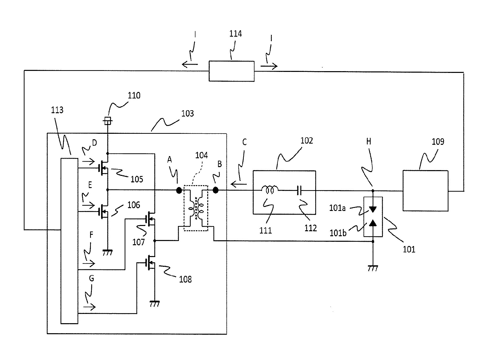
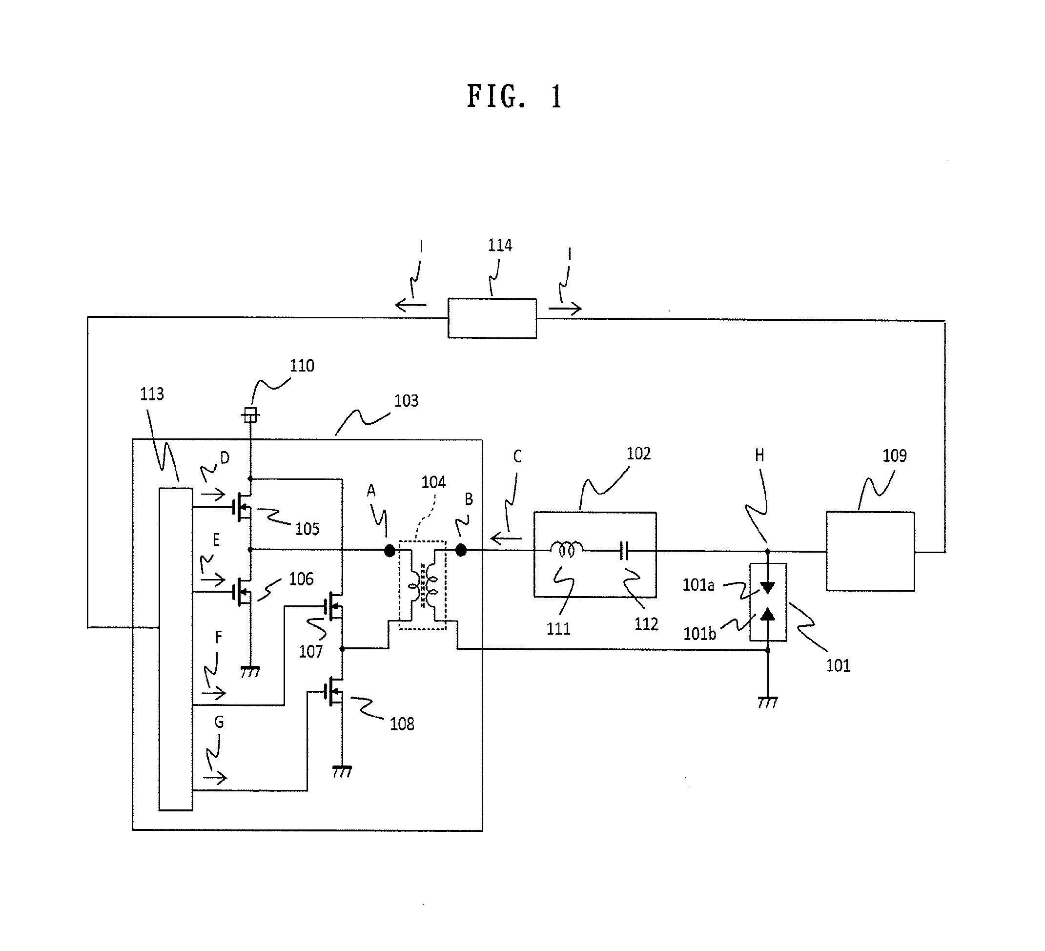
[0022]For this purpose, the ignition device includes, as shown in FIG. 1, an ignition plug 101 for igniting a combustible gas mixture within a combustion chamber of an engine, an ignition coil device 109 for applying a high voltage to the ignition plug 101 to initiate a spark discharge, an AC power source unit 103 for generating an AC current to flow in a path of the spark discharge, a boosting device 102, composed of a coil device 111 and a capacitor device 112, for boosting the output voltage of the AC power source unit 103 at an LC resonance point produced by the coi...

embodiment 2

[0042]While the bridge circuit of the AC power source unit 103 has been described above and illustrated in the drawings with the arrangement of a full bridge circuit with respect to the effect for the switching elements on the lower voltage side being made ON in Embodiment 1 of the present invention, the arrangement of the bridge circuit may also be that of a half bridge circuit.

[0043]Describing this by referring to FIG. 4, this half bridge circuit is composed of one pair of switching elements 120 and 121 connected in series between the high voltage side terminal and the low voltage side terminal of the DC voltage source 110, in which the winding of the transformer device 104 on the side of the AC power source unit 103 is connected between the connection points of the switching elements 120, 121 and ground, i.e. between the anode-cathode of the switching element 121.

[0044]In operation, when the capacitance discharging current C flows from the capacitor device 112 into the AC power s...


PUM


Abstract

In an ignition device, at a timing of a control signal provided by a control device to control an ignition coil device or at a timing prior to the control signal in order that a high voltage is applied to an ignition plug to initiate a spark discharge, a control circuit of an AC power source unit in response to the control signal controls switching elements composing a bridge circuit in the AC power source unit for a DC-AC inversion to thereby short-circuit a winding of a transformer device on the side of the AC power source unit, connected between a boosting device including a capacitor device and the bridge circuit for the circulation of a capacitance discharging current from the boosting device to the transformer device.

Description

BACKGROUND OF THE INVENTION[0001]1. Field of the Invention[0002]The present invention relates to an ignition device and in particular to an ignition device for high frequency discharge, used in the operation of an internal combustion engine.[0003]2. Description of the Related Art[0004]In recent years, problems of environmental conservation or fuel depletion have been posed, and there is a pressing need even in the automobile industry for countermeasures for those problems. As one example of such countermeasures, there is a method of improving fuel consumption dramatically by down-sizing and reducing weight of engines using superchargers.[0005]It has been known that in a highly supercharged state, the pressure in the combustion chamber of an engine becomes very high even in a state where combustion has not started and that a spark discharge for starting the combustion is difficult to initiate. One of the reasons is that the voltage required to cause an insulation breakdown at the gap...

Claims


Application Information

Patent Timeline
Patent Type & Authority Applications(United States)
IPC IPC(8): H01T15/00F02P5/145
CPCF02P5/145H01T15/00F02P3/01F02P3/04F02P9/007F02P11/00F02P15/10
Inventor MURAMOTO, YUICHITANAYA, KIMIHIKO
Owner MITSUBISHI ELECTRIC CORP
Why Eureka
Try Eureka