Thermal barrier materials and coatings with low heat capacity and low thermal conductivity

a technology of thermal conductivity and thermal conductivity, applied in the direction of climate sustainability, synthetic resin layered products, machines/engines, etc., can solve the problems of low damage tolerance, low heat capacity, and achieve low damage tolerance and low thermal conductivity

Active Publication Date: 2016-07-07
HRL LAB
View PDF8 Cites 21 Cited by
  • Summary
  • Abstract
  • Description
  • Claims
  • Application Information

AI Technical Summary

Benefits of technology

[0041]Other variations provide a method of forming a freestanding thermal barrier material, the method comprising combining a coating precursor with a spaceholder, and then removing at least a portion of the spaceholder to generate a three-dimensional microstructure comprising one or more metals and/or one or more ceramics, wherein the microstructure is porous with at least 60% void volume fraction and with closed porosity, and wherein the microstructure has a thermal conductivity of less than 10 W/m·K at 25° C. and a volumetric heat capacity of less than 1000 kJ/m3·K at 25° C.
[0042]In some embodiments, the metho

Problems solved by technology

For such an application, low thermal conductivity and low heat capacity is required.
Both types of cellular architecture are detrimental to structural integrity, and the brittle ceramic material causes low damage tolerance.
Another disadvantage is that both cellular architectures are fairly open and gases from the outside can access many of the pores and even the underlying substrate.
Shuttle tiles exhibit low thermal conductivity a

Method used


Image

  • Thermal barrier materials and coatings with low heat capacity and low thermal conductivity
  • Thermal barrier materials and coatings with low heat capacity and low thermal conductivity
  • Thermal barrier materials and coatings with low heat capacity and low thermal conductivity

Examples


example 1

Sintered Inconel Spheres

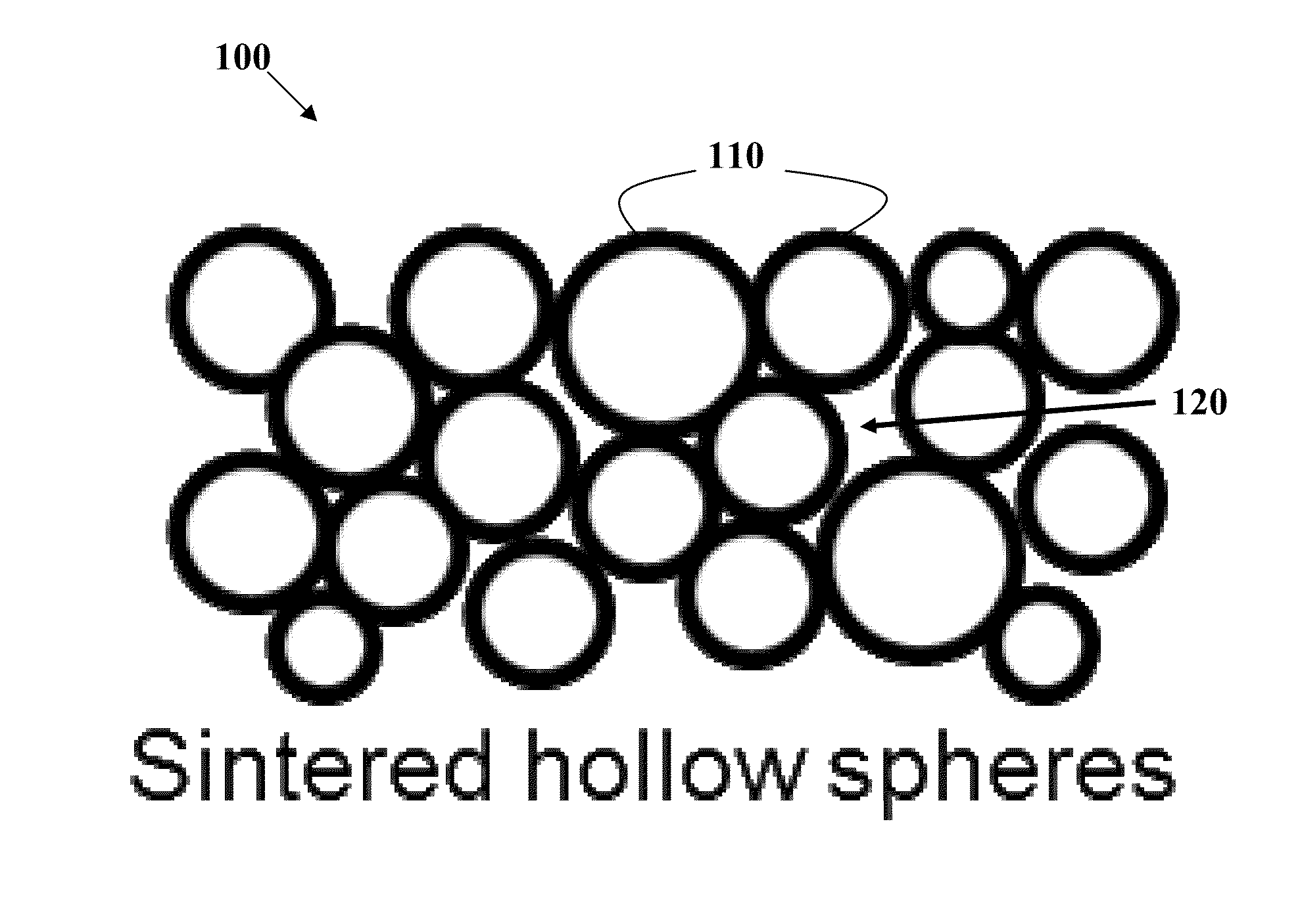
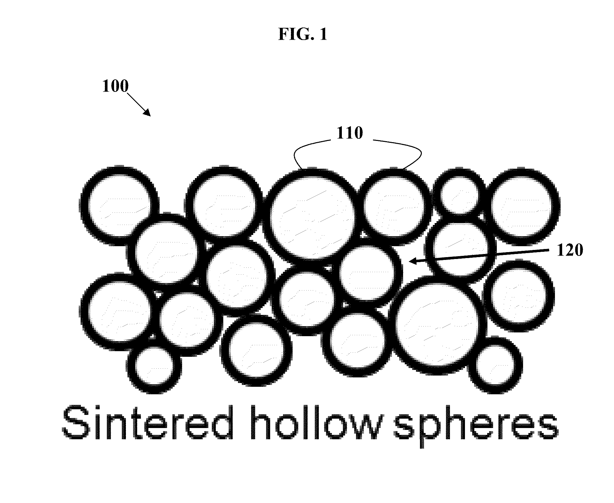
[0146]One example of this invention is a material comprising sintered hollow nickel alloy (Inconel 718) spheres with a diameter of 50 microns and a wall thickness of 1.0 micron, with a diameter to wall thickness ratio of 50. This microstructure (as depicted in FIG. 1) exhibits a calculated thermal conductivity of 0.12 W / m·K and heat capacity of 290 kJ / m3·K. The thermal conductivity and heat capacity are calculated (not considering radiation and convection) according to Solórzano et al., “Thermal Properties of Hollow Spheres,”Multifunctional Metallic Hollow Sphere Struct., pp. 89-107 (2009) which is incorporated by reference herein. For Inconel 718, a thermal conductivity of 11 W / m·K and heat capacity of 3900 kJ / m3·K is used in estimating the thermal conductivity and heat capacity of sintered spheres. For comparison, conventional zirconia-based thermal barrier coatings used in the aviation industry have thermal conductivities around 0.8 W / m·K and heat capaciti...

example 2

Sintered Hollow Glass Spheres

[0149]FIGS. 4-7 are collectively a schematic flowchart of sintered hollow spheres material fabrication. Hollow glass spheres (silica, soda-lime, borosilicate, aluminosilicate, etc.) 410 are fused into a thin layer 420 by heating 430 above the glass transition temperature (FIG. 4), creating a closed-cell structure with high porosity similar to the schematic in FIG. 1. Spheres 510 are fused to adjacent spheres at flattened points of contact, leaving open space 520 between the spheres, as well as space 530 inside them (FIG. 5). The resulting structure has a large (>60%) open volume fraction, creating a material with low heat capacity and low thermal conductivity and relatively high crush strength. The properties can be tailored by selecting hollow spheres with different diameter and wall thickness.

[0150]A ductile, corrosion-resistant and oxidation-resistant cover layer 620 is added by induction melting of a thin nickel sheet onto the top surface of the poro...

example 3

Flotation Co-deposition of Hollow Glass Spheres in a Nickel Matrix

[0152]Hollow glass spheres are incorporated into a nickel matrix at a high volume fraction through flotation co-deposition. A commercial nickel sulfamate plating solution is used to electrodeposit the nickel. A schematic of the flotation co-deposition process setup is shown in FIG. 9. Hollow glass spheres 910 are added directly to 300 mL of plating solution 920 at a concentration of 3 g / L. The mixture is stirred continuously and heated to 65° C. After reaching temperature, the majority of the added hollow glass spheres 910 have floated to the top. A copper cathode 930 is prepared by degreasing (alcohol) and acid activation (10% sulfamic acid). The cathode is immersed just below the surface of the floating glass spheres 910 and a current equivalent to 10 mA / cm2 is applied for 2 hours (anode 940).

[0153]While plating, the solution is periodically stirred by hand at the surface to replenish solution at the interface and f...


PUM

PropertyMeasurementUnit
Temperatureaaaaaaaaaa
Fractionaaaaaaaaaa
Fractionaaaaaaaaaa

Abstract

Thermal barrier materials are provided that possess low heat capacity and low thermal conductivity, while at the same time, high structural integrity and robustness. In some embodiments, the disclosed coating comprises metal-containing spheres that are sintered or glued together and/or embedded in a matrix. The coating has at least 60% void volume fraction and closed porosity. The coating thickness is from 50 microns to 500 microns, and the metal spheres have an average diameter that is from about 5% to about 30% of the coating thickness. In some embodiments, the metal spheres have an average diameter that is 4-10 times smaller than the coating thickness. Thermal barrier materials with these coatings can be beneficial in engine applications, for example.

Description

PRIORITY DATA[0001]This patent application is a non-provisional application with priority to U.S. Provisional Patent App. No. 61 / 880,247 filed Sep. 20, 2013, which is hereby incorporated by reference herein.FIELD OF THE INVENTION[0002]The present invention generally relates to thermal barrier materials and coatings.BACKGROUND OF THE INVENTION[0003]Thermal barrier coatings are highly advanced material systems usually applied to metallic surfaces, such as gas turbines or aero-engine parts, operating at elevated temperatures, as a form of exhaust heat management. These coatings serve to insulate components from large and prolonged heat loads by utilizing thermally insulating materials which can sustain an appreciable temperature difference between the load-bearing alloys and the coating surface. In doing so, these coatings can allow for higher operating temperatures while limiting the thermal exposure of structural components, extending part life by reducing oxidation and thermal fatig...

Claims


Application Information

Patent Timeline
IPC IPC(8): C23C30/00B22F1/00C22C1/04C22C19/05C04B35/64C04B35/622B22F1/0655
CPCC23C30/00C04B35/64C04B35/62222B22F1/0051C22C19/056C22C19/055C22C1/0433C04B41/009C04B41/4582C04B41/50C04B41/85C04B2111/00982C04B2111/763B22F1/0655C04B35/00C04B41/0072C23C26/00C23C24/085C23C24/103C25D1/08C25D1/12C25D3/12C25D15/00C23C18/1648C23C18/1662C23C18/1657F01D5/288F05D2300/514F05D2230/90Y02T50/60
Inventor SCHAEDLER, TOBIAS A.GROSS, ADAM F.NOWAK, ANDREW P.MARTIN, JOHN A.KOLODZIEJSKA, JOANNA A.
Owner HRL LAB
Why Eureka
Try Eureka