Miniature ultrasonic imaging system

a technology of ultrasonic imaging and micro-machine, applied in ultrasonic/sonic/infrasonic image/data processing, mechanical vibration separation, application, etc., can solve the problems of multiple error sources, lack of fitness usage devices capable of monitoring local muscle building effectiveness, and currently available blood pressure gauge devices (sphygmomanometers) are difficult to use without calibration and proficiency training, and achieve the effect of facilitating cosmetic supervision

Active Publication Date: 2016-09-15
RGT UNIV OF CALIFORNIA
View PDF0 Cites 24 Cited by
  • Summary
  • Abstract
  • Description
  • Claims
  • Application Information

AI Technical Summary

Benefits of technology

[0019]3. Local body-part ultrasonic imaging, including: (a) performing ultrasonic imaging on local body part for preventive investigations; (b) performing ultrasonic imaging on eye lens for myopia diagnosis; and (c) performing ultrasonic imaging on skin for determining skin-aging and facilitating cosmetic supervision.

Problems solved by technology

A weight scale integrated with impedance measuring devices provide a coarse full-body measurement on both weight and body-fat percentage, but are susceptible to multiple error sources, including humidity.
There is also a lack of fitness usage devices capable of monitoring local muscle building effectiveness.
Currently available blood pressure gauge (sphygmomanometer) devices are difficult to use without calibration and proficiency training.
A combination of these devices (weight, body-fat percentage and blood pressure) using currently available technology would clearly be excessively bulky for a portable device, and thus do not represent a workable solution for personal-health monitoring.
The accuracy and local-body part measuring using ultrasonics overcomes many problems of traditional devices, while the size, complexity and huge power consumption of these devices remains an issue.
The current problems preventing further miniaturize and integration of ultrasonic imaging include: (a) large and expensive ultrasonic transducer elements; (b) high-voltage requirements for driving the transducers; (c) requirements for multiple power supplies; and (d) lack of efficient level-shifting schemes from low voltage to high voltage.

Method used


Image

  • Miniature ultrasonic imaging system
  • Miniature ultrasonic imaging system
  • Miniature ultrasonic imaging system

Examples


embodiment 10

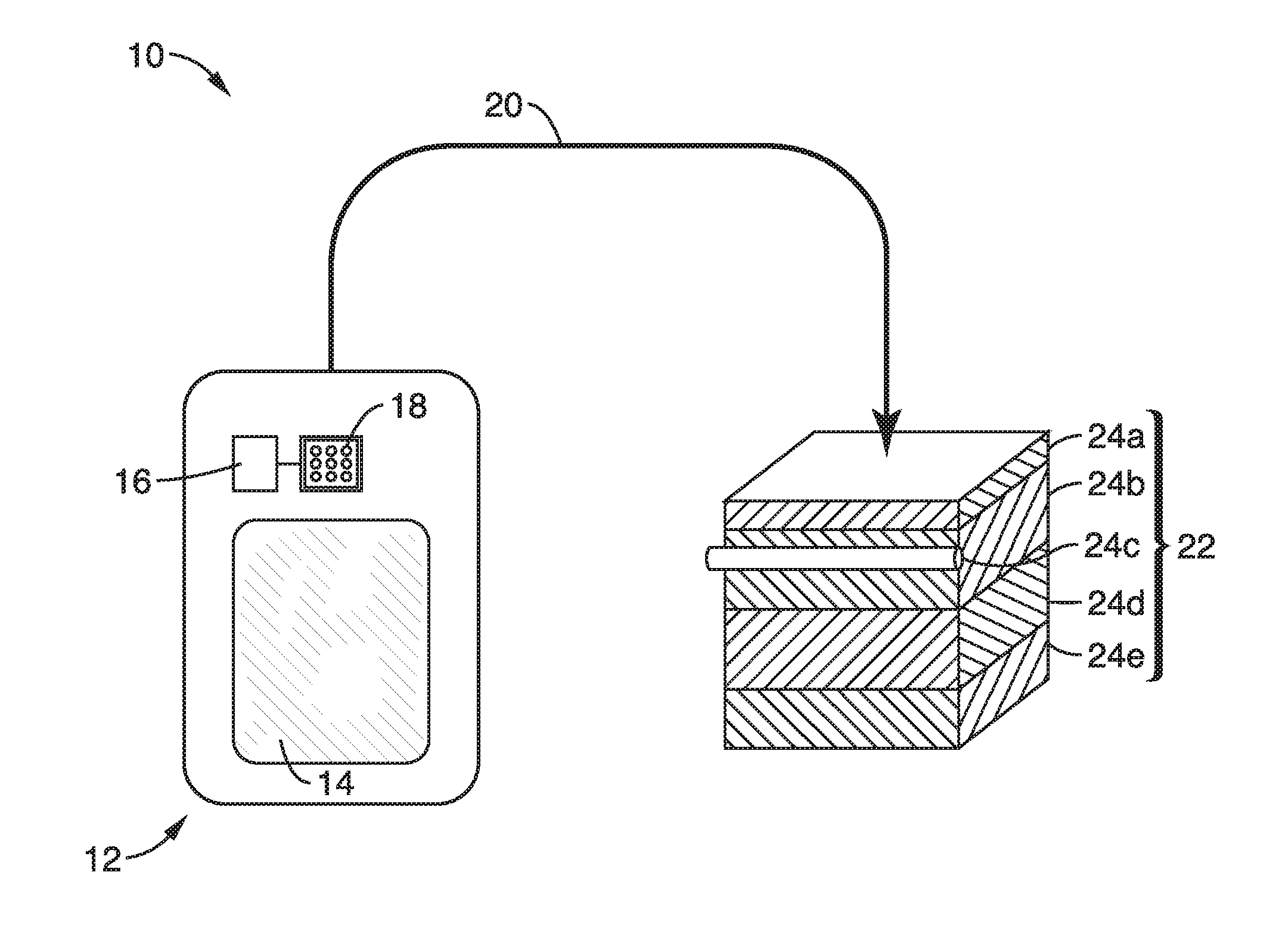
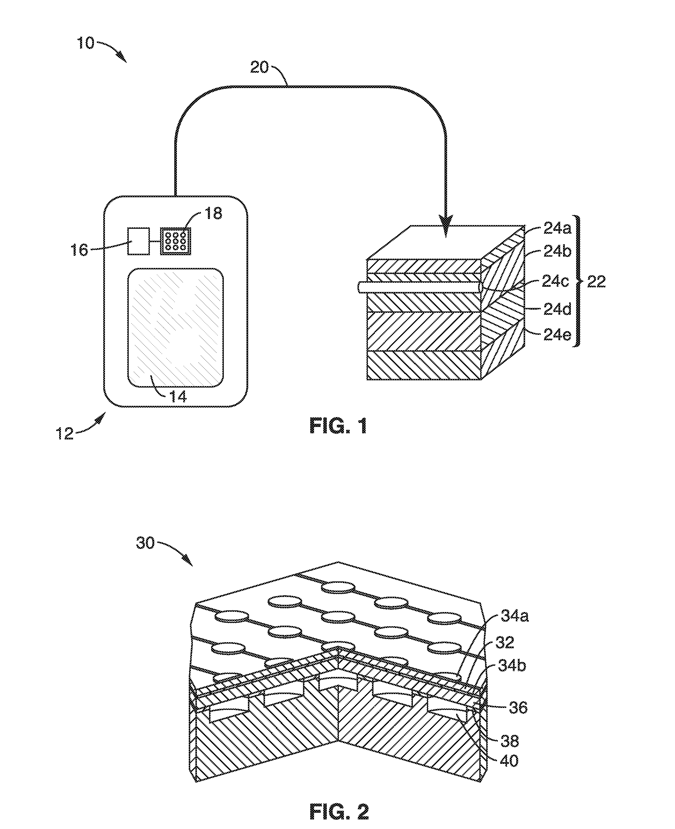
[0031]FIG. 1 illustrates an embodiment 10 of an ultrasonic imaging system. By way of example, a portable device 12, having display 14 (e.g., touch screen) is shown with an ultrasonic imager circuit to emit ultrasonic waves. Display screen 14 may also provide touch input for user I / O, such as for supporting a graphical user interface (GUI), or other user interfacing. The ultrasonic imager comprises an ultrasonic imaging sensor array 18 coupled to a processor 16, such as within an application specific integrated circuit (ASIC), which may be coupled to (mounted upon) the portable electronic device and / or integrated within it.

[0032]During operation, the user contacts the imager 18, to a local body part area 22, upon which ultrasonic wave are emitted (transmitted) into that area of the patient's body. Arrow 20 merely represents the movement of imager 18 to achieve contact with body area 22. The imager collects (receives) the reflected sound wave signal and the processor processes the ima...

embodiment 30

[0036]In FIG. 2 a cutaway of a PMUT embodiment 30 is shown having a piezoelectric layer 32, over which is disposed a top electrode pattern 34a. Beneath the piezoelectric layer 32 there is shown a bottom electrode 34b, and a device semiconductor 36 (e.g., Si depicted by way of example), followed by dielectric regions 38 (e.g., SiO2), and cavities 40.

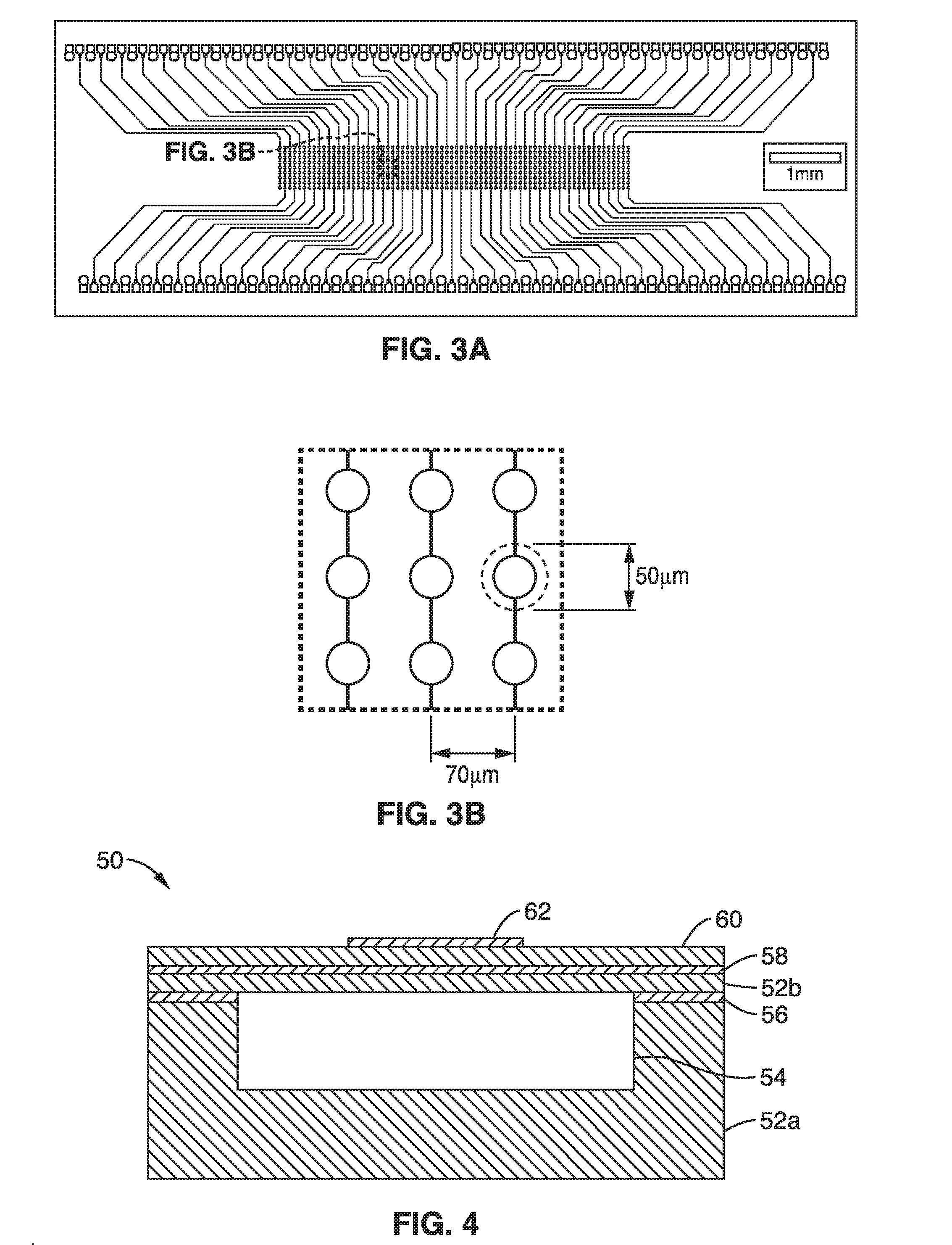
[0037]FIG. 3A and FIG. 3B show a trace pattern of a PMUT ASIC as seen in FIG. 3A, with electrode areas magnified in FIG. 3B, shown with example electrode area of 50 μm, and a pitch (spacing between electrodes) of 70 μm.

embodiment 50

[0038]FIG. 4 illustrates an embodiment 50 of a PMUT showing a single electrode 62 over a cavity region 54. A material substrate 52a (e.g., Si) is shown into which a cavity 54 is formed, typically by a subtractive process (i.e., etching), over which is deposited a dielectric layer 56 (e.g., SiO2), above which is another material layer 52b (e.g., Si), bottom electrode 58, piezoelectric layer 60, upon which electrode 62 is disposed.

[0039]FIG. 5 illustrates an an ultrasonic sensor 70 comprising a low voltage supply 72 and digital control block 74 supplying power and control to an ASIC array 76, shown coupled to a PMUT transducer array 77. Output from ASIC 76 is shown being received at an analog-to-digital converter (ADC) 78 before receipt by at least one processing element 80 which processes the ultrasonic data to generate image data, which can be processed as an image output 82 directed to a display. It should also be recognized that the image data can be processed to extract salient f...


PUM


Abstract

An ultrasonic imaging apparatus having a Micro-machined Ultrasonic Transducer (MUT), such as a Piezoelectric MUT (PMUT) or Capacitive MUT (CMUT), with a transmitting mode and a receiving mode for generating and sensing acoustic pressure in imaging applications. During transmission in a PMUT the inverse piezoelectric effect on the piezo layer causes transverse stress, which causes a bending moment in the PMUT structure leading to out-of-plane deflection. Different applied signs of voltage generates different signs of stress inside the piezo that in turn cause oscillating motion generating an acoustic pressure wave. During signal reception, incident pressure waves deflect the PMUT creating transverse stress, resulting in a charge determined through measuring voltage between electrodes. The apparatus is particularly well-suited for use in health care, such as measuring fat/muscle thickness, blood-flow, and blood pressure.

Description

CROSS-REFERENCE TO RELATED APPLICATIONS[0001]This application claims priority to, and the benefit of, U.S. provisional patent application Ser. No. 62 / 130,778 filed on Mar. 10, 2015, incorporated herein by reference in its entirety.INCORPORATION-BY-REFERENCE OF COMPUTER PROGRAM APPENDIX[0002]Not ApplicableNOTICE OF MATERIAL SUBJECT TO COPYRIGHT PROTECTION[0003]A portion of the material in this patent document is subject to copyright protection under the copyright laws of the United States and of other countries. The owner of the copyright rights has no objection to the facsimile reproduction by anyone of the patent document or the patent disclosure, as it appears in the United States Patent and Trademark Office publicly available file or records, but otherwise reserves all copyright rights whatsoever. The copyright owner does not hereby waive any of its rights to have this patent document maintained in secrecy, including without limitation its rights pursuant to 37 C.F.R. §1.14.STATE...

Claims


Application Information

Patent Timeline
Patent Type & Authority Applications(United States)
IPC IPC(8): A61B8/00A61B8/06A61B8/08A61B8/04
CPCA61B8/4483A61B8/5207A61B8/06A61B8/04B06B1/0662
Inventor BOSER, BERNHARD E.HORSLEY, DAVID A.TANG, HAO-YENLU, YIPENG
Owner RGT UNIV OF CALIFORNIA
Why Eureka
Try Eureka