Noncontact Three-dimensional Diffuse Optical Imaging of Deep Tissue Blood Flow Distribution

a diffuse optical imaging and deep tissue technology, applied in the field of diffuse correlation tomography, can solve problems such as the risk of infection of vulnerable tissues, the failure of successful execution of diagnostics, and the inability to accurately detect the presence of infection in the blood stream of the deep tissue,

Active Publication Date: 2016-09-29
UNIV OF KENTUCKY RES FOUND
View PDF2 Cites 37 Cited by
  • Summary
  • Abstract
  • Description
  • Claims
  • Application Information

AI Technical Summary

Benefits of technology

[0019]The present invention also provides in part for creating a 3D solid model of the tissue being imaged by first acquiring autocorrelation functions at each measurement location of the S-D array; and then acquiring a surface geometry of the tissue with a 3-D camera that includes the boundaries of the region of interest. Following such...

Problems solved by technology

The ability to image within diseased or sensitive tissue is highly desirable as it provides further information as to the underlying health of the tissue, but remains problematic in successful execution due to accessing the tissue without touching the surface.
Significant problems with contact measurements (using a probe in contact with tissue) include the risk for infection of vulnerable tissues (e.g., wounds, burns, reconstructive tissue flaps) and the deformation of soft tissues (e.g., breasts) distorting blood flow and oxygenation.
Chronic wounds affect over 5 million Americans each year, resulting in over $20 billion in health care costs.
Patients afflicted with chronic wounds suffer from physical pain and disabilities in addition to psychological and emotional stresses and poor quality of life.
Multiple factors can lead to impaired wound healing.
Constant pressure against the tissue reduces blood supply to that area which results in tissue ischemia1, 2.
Burns can cause swelling, blistering, scarring and, in serious cases, shock and even death.
They also can lead to infections because they damage skin's protective barrier.
As a further example, mastectomy skin flap necrosis may ultimately lead to implant exposure, infection and implant loss.
In some of these cases, the complications may be so devastating as to cause a failure of reconstruction4,5,6.
Primary or salvage surgeries are exte...

Method used


Image

  • Noncontact Three-dimensional Diffuse Optical Imaging of Deep Tissue Blood Flow Distribution
  • Noncontact Three-dimensional Diffuse Optical Imaging of Deep Tissue Blood Flow Distribution
  • Noncontact Three-dimensional Diffuse Optical Imaging of Deep Tissue Blood Flow Distribution

Examples


examples

EX. 1: Noncontact Diffuse Optical Assessment of Blood Flow Changes in Head and Neck Free Tissue Transfer Flaps

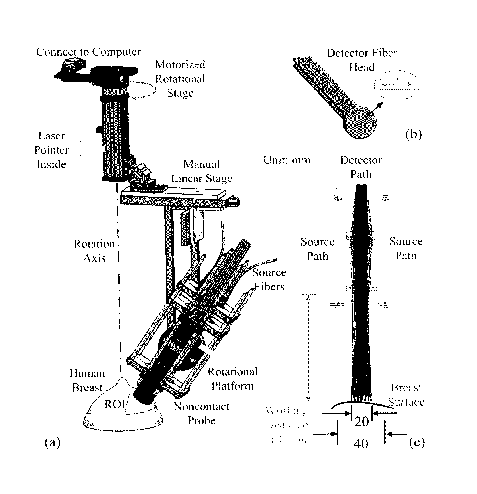
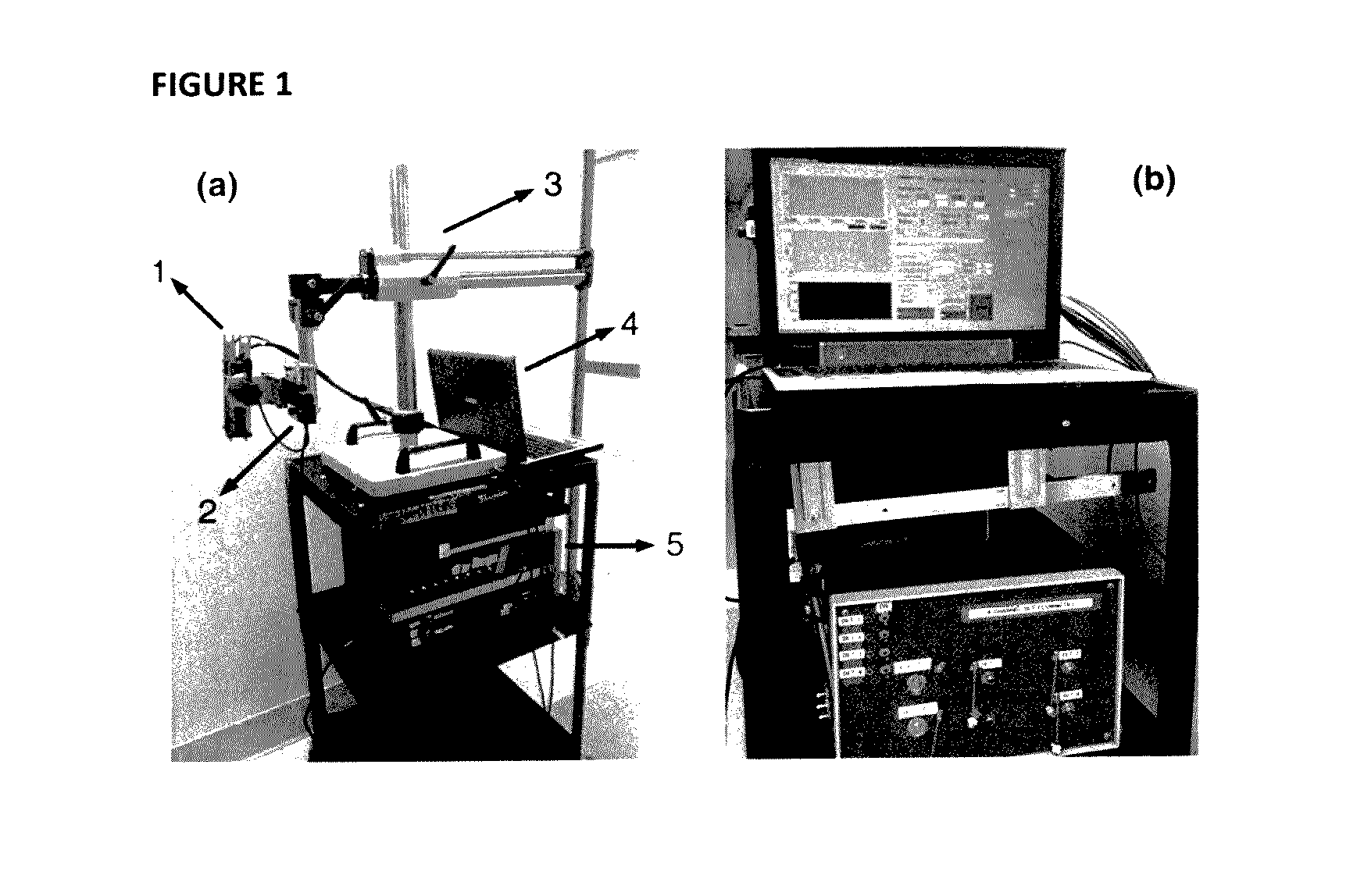
[0094]The custom-made ncDCS system for the noncontact measurement of tissue blood flow is shown in FIG. 1. A noncontact optical probe is held by a platform connected to a linear motorized stage. A multiple axis stand holder provides free movements to adjust the location and incident angle of the probe. A DCS flowmetry is controlled by a laptop for continuous monitoring of tissue blood flow as soon as the noncontact probe is aligned over the target tissue. The four-channel DCS device consists of a long-coherence-length (>5 m) NIR laser diode (785 nm, 100 mW, CrystaLaser Inc, California), four single-photon-counting avalanche photodiodes (APDs, Perkin Elmer, Canada), and a four-channel correlator (correlator.com, New Jersey). The ncDCS system is integrated compactly and portably to ensure convenient operation in both operating and patient rooms.

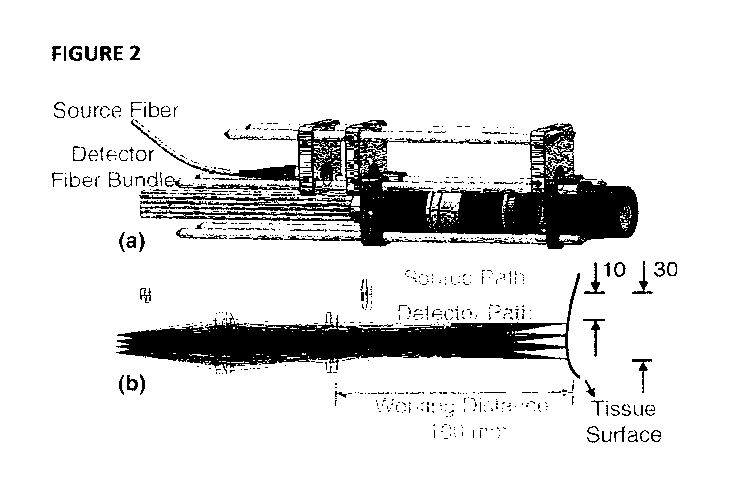
[0095]FIG. 2(a) shows the detail...


PUM


Abstract

The present invention provides for three-dimensional reflectance diffuse optical imaging of deep tissue blood flow distribution that removes the need for probe-tissue contact, thereby allowing for such technology to be applied to sensitive, vulnerable, damaged, or reconstructive tissue. The systems utilize noncontact application and detection of near-infrared light through optical lens and detection through a linear array or two-dimensional array of avalanche photodiodes or a two-dimensional array of detectors provided by charge-coupled-device (CCD). Both further feature a finite-element-method (FEM) based facilitation to provide for three-dimensional flow image reconstruction in deep tissues with arbitrary geometries.

Description

RELATED APPLICATIONS[0001]This application claims priority to U.S. Provisional Application 62 / 136,707, filed Mar. 23, 2015, which is hereby incorporated by reference in its entirety.GOVERNMENT SUPPORT[0002]This invention was made with government support under grants R21-AR062356 and UL-1RR033173 Pilot Grant awarded by the National Institutes of Health. The government may have certain rights in the invention.FIELD OF THE INVENTION[0003]The present invention relates to the application of diffuse correlation tomography (DCT) through both noncontact (ncDCT) and charge-coupled-device (CCD)-based noncontact speckle contrast (nc_scDCT) approaches for three-dimensional (3-D) reflectance imaging of deep tissue (up to 1.5 cm depth) to better assess any potential tissue injury therein.BACKGROUND[0004]The ability to image within diseased or sensitive tissue is highly desirable as it provides further information as to the underlying health of the tissue, but remains problematic in successful exe...

Claims


Application Information

Patent Timeline
IPC IPC(8): A61B5/00A61B5/026
CPCA61B5/7275A61B5/7282A61B5/0261A61B5/0073A61B5/0075A61B5/0091A61B5/708A61B5/7214G16H50/50G01N2021/1787G06F30/00
Inventor YU, GUOQIANGLIN, YUHUANG, CHONG
Owner UNIV OF KENTUCKY RES FOUND
Why Eureka
Try Eureka