
Dynamic Point-the-bit Rotary Steerable Drilling Tool and Measuring Method Thereof

Active Publication Date: 2016-09-29
CHINA UNIV OF PETROLEUM (EAST CHINA)
View PDF0 Cites 5 Cited by
  • Summary
  • Abstract
  • Description
  • Claims
  • Application Information

AI Technical Summary

Benefits of technology

This patent is about a system for supplying power and communication to a drilling tool used in oil drilling. The system uses a power management module, a voltage regulator, and an electromagnetic coupler to supply power to the main circuit board, auxiliary circuit board, and attitude sensor. This avoids the need for mechanical friction for power and signal transmission, making it more reliable and stable. Additionally, the patent describes a method to measure the speed of the drilling tool using a magnetic grid speed encoder, which can directly output square signals. The patent also mentions the use of a bias adjusting mechanism and a lubrication system for the drilling tool to ensure proper operation and reduce wear and tear.

Problems solved by technology

However, the drilling fluid passage is designed by means of annulus, at the same time, a signal processing method and a transmission mode of the sensor haven't been detailed, and the annulus fluid passage design method required complicated dynamic seal and reliability is hard to guaranteed.
We can find its defects that a tool housing is fixed, drilling pressure and toque cannot be used to the greatest extent, and the structural bending angle is changed depending on adjustment of bending angle of a mandrel, which adds load to a motor and causes damage of the mandrel borne high-intensity alternating stress for a long time during adjustment of the structural bending angle.
We can find its defects that the inner and outer eccentric rings of a double-eccentric-ring adjusting mechanism adopted in this invention are driven and adjusted by a servo motor, and the outer eccentric ring is embedded in the stabilized platform, thereby being not compact enough and adding design difficulty to a power supply mechanism of the stabilized platform; a conductive slip ring adopted in this invention supplies power for a power device but it will go wrong in case of violent vibration during drilling; absence of the pressure tubing in the drilling fluid passage requires dynamic seal in the positions of the coupler and the offsetting mechanism, which is substantially unreliable.
But it still has its defects that the offsetting mechanism is driven by a hydraulic piston and is not compact enough, the axial displacement of the drilling bit shaft cannot be compensated when the offsetting mechanism is located in the maximum bending angle, and absence of the pressure tubing in the drilling fluid passage requires dynamic seal in the positions of the coupler and the offsetting mechanism, which is substantially unreliable; only the control method is included in this invention but specific mounting methods of the sensor are not mentioned; a conductive slip ring adopted in this invention supplies power for a power device but it is unreliable in case of violent vibration during drilling.
However, it has its defects that a double-torque motor used for controlling the stabilized platform is complicated in structure; a force control method used in this invention is easy to cause speed fluctuation of the stabilized platform; working frequency of a non-contact electromagnetic coupler and distance between the primary side and the auxiliary side during mounting are not elaborated in its specification; power is supplied by a storage battery which is poor in durability and has limited operating time; signal transmission of the stabilized platform sensors depends on a non-contact high-frequency coupling transformer, signal modulation and demodulation are complicated.

Method used


Image

  • Dynamic Point-the-bit Rotary Steerable Drilling Tool and Measuring Method Thereof
  • Dynamic Point-the-bit Rotary Steerable Drilling Tool and Measuring Method Thereof
  • Dynamic Point-the-bit Rotary Steerable Drilling Tool and Measuring Method Thereof

Examples


Embodiment Construction

[0047]Referring now to the drawings for more details.

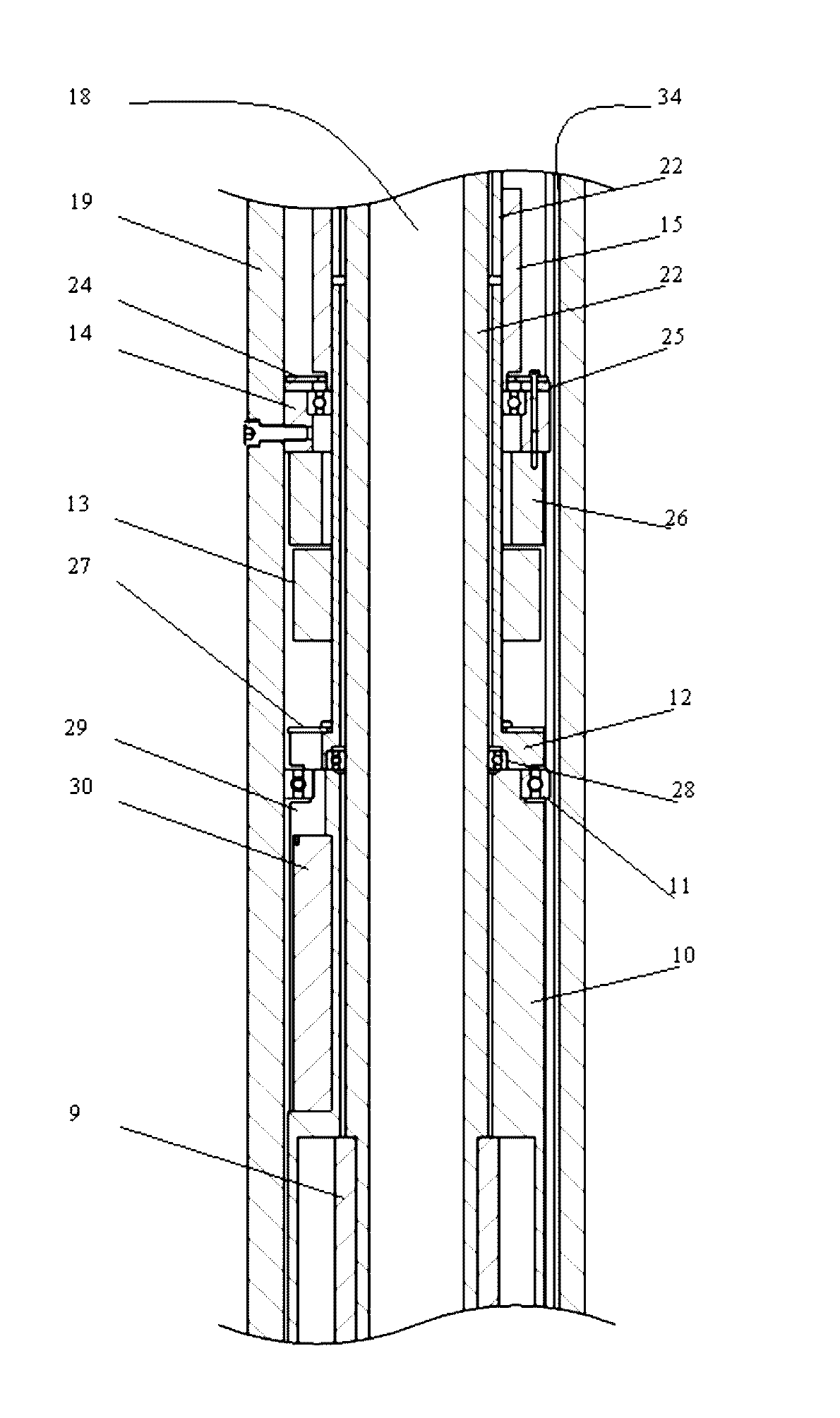
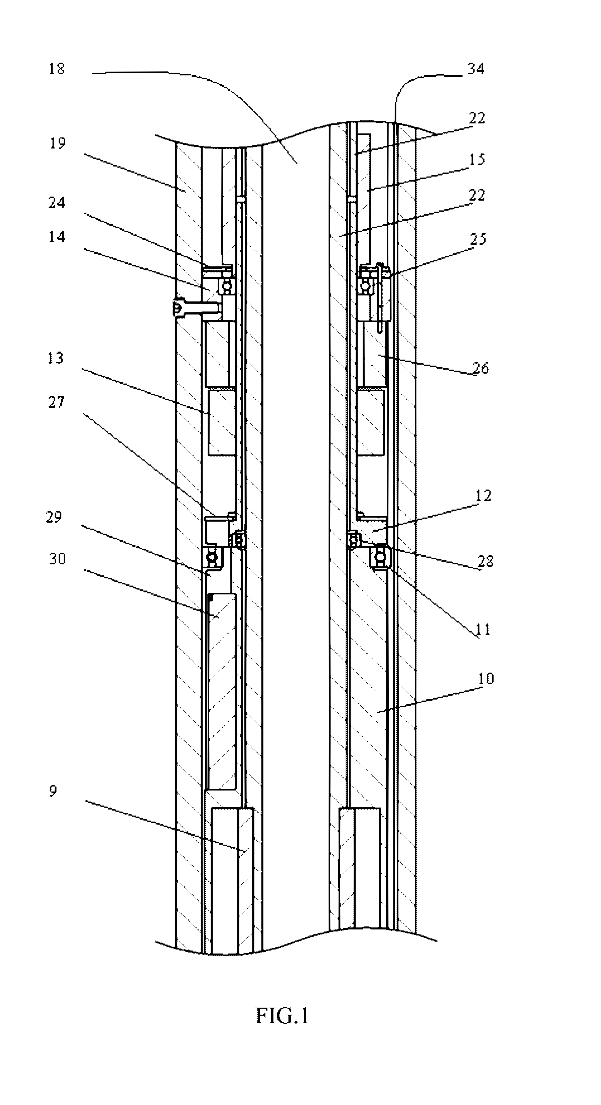
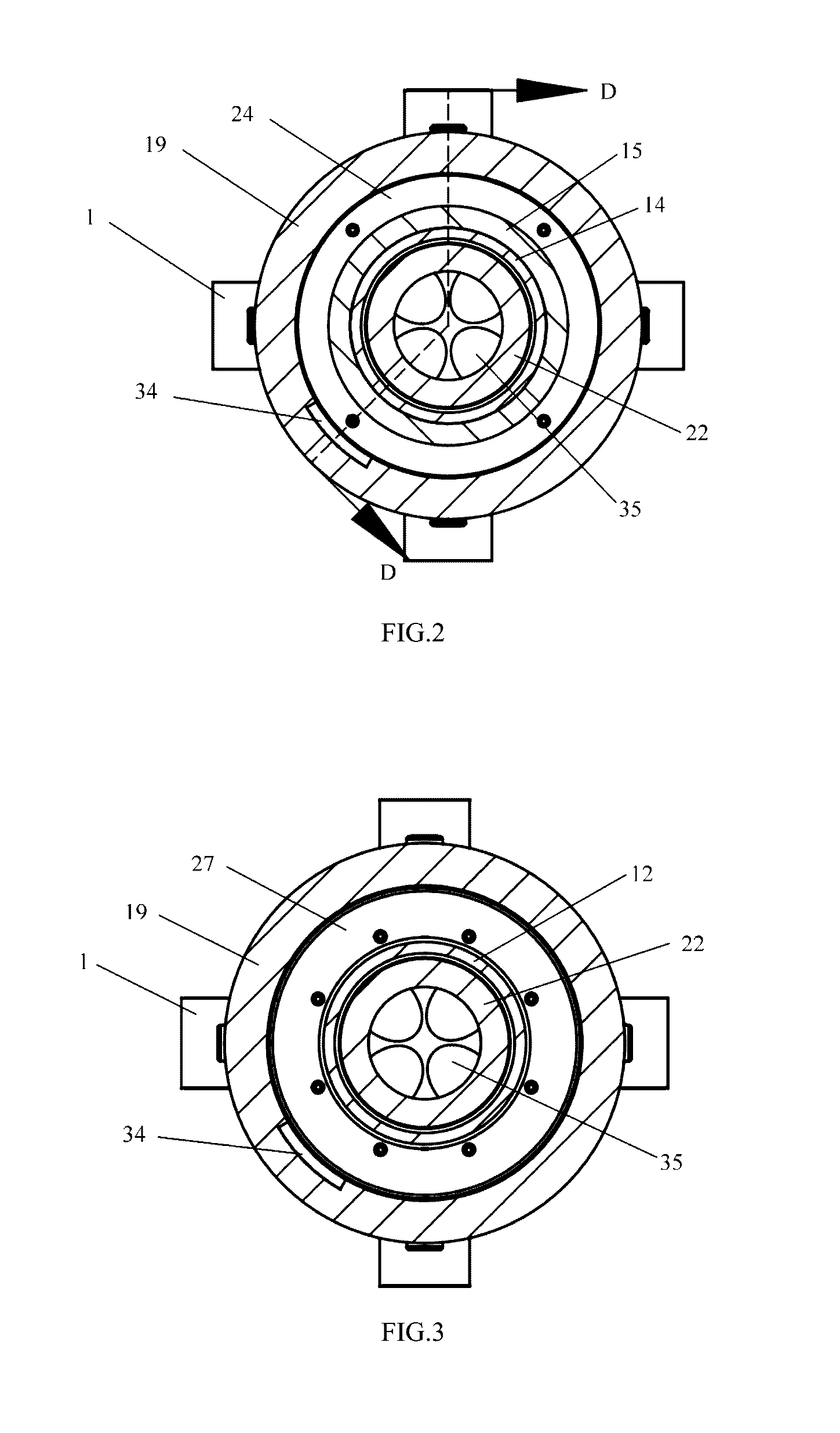
[0048]As shown in FIG. 1, a dynamic point-the-bit rotary steerable drilling tool comprises a rotary housing 19, a stabilized platform assembly 37, a hollow servo-motor assembly 16, a drilling fluid passage 18, an inner eccentric ring 31, an outer eccentric ring 7, a drilling bit shaft 5 and a universal joint 38. The stabilized platform assembly comprises a stabilized platform body 10 mounted in the rotary housing 19 and a stabilized platform upper-end cover 12 connected with the stabilized platform body 10, a stabilized platform upper bearing 11 is fixed between the stabilized platform body 10 and the stabilized platform upper-end cover 12, the upper end of the stabilized platform upper-end cover 12 is connected with the hollow servo-motor assembly 16 via a coupler 15, the absolute speed and the toolface angle of the stabilized platform are controlled by the hollow servo-motor assembly 16, and the lower end of the stabilized platf...


PUM


Abstract

The invention relates to a dynamic point-the-bit rotary steerable drilling tool and a measuring method thereof. The dynamic point-the-bit rotary steerable drilling tool comprises a rotary housing, a stabilized platform assembly, a hollow servo-motor assembly, a drilling fluid passage, an inner eccentric ring, an outer eccentric ring, a drilling bit shaft and a universal joint. The dynamic point-the-bit rotary steerable drilling tool also comprises a stabilized platform communication and power supply system which includes an instrument storehouse fixed at the upper end of the rotary housing, a main circuit board, an auxiliary circuit board mounted on the stabilized platform upper-end cover, an electromagnetic coupler primary-side, an electromagnetic coupler secondary winding and an electromagnetic coupler primary-side mounting plate fixed at the lower end of a coupler. The main circuit board is mounted on the electromagnetic coupler primary-side mounting plate, the electromagnetic coupler secondary winding is connected with the auxiliary circuit board, and the auxiliary circuit board is connected with the attitude sensor mounted on the side wall of the upper end of the stabilized platform body. By the dynamic point-the-bit rotary steerable drilling tool, hollow drilling fluid passage, power supply and signal transmission of the stabilized platform sensor, attitude angle parameter measurement and toolface angle real-time control of the rotary steerable drilling tool are realized.

Description

FIELD OF THE INVENTION[0001]The invention relates to the technical field of drilling of petroleum and natural gas, in particular relates to a dynamic point-the-bit rotary steerable drilling tool and a measuring method thereof.BACKGROUND OF THE INVENTION[0002]The rotary steerable drilling tool is an important part for implementing closed-loop steerable drilling and reflects the highest development level of existing rotary steerable drilling tools. The existing rotary steerable drilling tools are classified into push-the-bit and point-the-bit types according to steering ways and into dynamic and static types according to action ways of the bias unit. Compared with other rotary steerable drilling techniques, the dynamic point-the-bit rotary steerable drilling technique can keep the drilling tool at full-rotation states, so as to effectively reduce sliding friction resistance and enhance displacement extension and better hole quality. The dynamic point-the-bit rotary steerable drilling ...

Claims


Application Information

Patent Timeline
IPC IPC(8): E21B44/00E21B17/02E21B47/12E21B47/024E21B7/06E21B4/20
CPCE21B44/005E21B7/068E21B17/028E21B47/122E21B47/024E21B4/20
Inventor WANG, WEILIANGGENG, YANFENGYAN, ZHIDAN
Owner CHINA UNIV OF PETROLEUM (EAST CHINA)
Learn More