X-ray pulse source and method for generating x-ray pulses

a pulse source and x-ray technology, applied in the direction of accelerators, laser details, electric discharge tubes, etc., can solve the problems of low brilliance of high photon energy, low photon energy relative low, and inability to achieve hard x-ray range, etc., to achieve short undulator lengths, less power and operating costs, and less facility costs

Active Publication Date: 2016-11-03
DEUTES ELEKTRONEN SYNCHROTRON DESY
View PDF4 Cites 8 Cited by
  • Summary
  • Abstract
  • Description
  • Claims
  • Application Information

AI Technical Summary

Benefits of technology

[0067]Accordingly, the inventive X-ray pulse source comprises a THz-driven electron source combined with an electromagnetic interaction device, in particular an electromagnetic undulator. The inventive X-ray pulse source does not include a static magnetic undulator. On the contrary, the electromagnetic undulator is provided with periods from the THz to optical range, and eventually adapted for coherent inverse Compton scattering, with a period on the order of 100 μm to 1 μm, which leads up to 10,000 times shorter undulator lengths compared to the length of magnetic undulators in conventional FEL based X-ray sources. This in turn allows reduction of electron beam energy from 10 GeV to 50 MeV to reach sub-Angstrom radiation. Therefore, the invention is capable of providing a compact X-ray source with a characteristic extension, e. g. length in a range of 1 m to 10 m, with correspondingly thousand times less facility costs overall. In other words, the X-ray source size can be much smaller than a typical FEL size by as much as a factor of 1000 to 10000. Similarly, the power and operating cost to operate such a device is 1000 to 10000 times less. Due to the lower cost it will open up many applications currently only possible at large-scale facilities.
[0068]The advantage of this invention in comparison to the conventional HHG technique is that the inventive technique scales well into the hard X-ray range, which is technically much more important than EUV, because it enables spatial resolution in the atomic scale. Contrary to the HHG technique, the invention enables spatio-temporal investigation with atomic spatial resolution and femtosecond, e. g. less than 10 fs, to attosecond temporal resolution.
[0069]According to a preferred embodiment of the invention, the photo-emitter device comprises a field emitter array.
[0070]Preferably, the electron pulses are generated by optical field emission. The term “field emitter array” refers to a planar arrangement of emitter tips providing the emitter portion of the photo-emitter device. Preferably, the field emitter array comprises a nanostructured photocathode. All emitter tips of the field emitter array are simultaneously exposed to the excitation pulses, so that a plurality of electrons are emitted from the field emitter array. Advantageously, with the controlled field emission of electrons from emitter tips and a compact driver device using THz acceleration a fully coherent X-ray source producing even attosecond pulses can be provided operating similar to a free-electron laser.
[0071]With the preferred use of coherent excitation pulses, a field emission threshold is obtained at all tips simultaneously, so that electron emission at the tips is synchronized.
[0072]Advantageously, this allows producing temporally and eventually even spatially correlated electron pulses resulting in a modulated electron beam that, preferably after further acceleration and compression, is modulated at the X-ray wavelength to be produced. The strength of the modulation determines the necessary length of the electromagnetic undulator to reach lasing and enables temporally fully coherent X-rays. If the beam is fully modulated the electromagnetic undulator can be short. This determines the necessary energy of the electromagnetic pulses provided by the electron pulse source device constituting the electromagnetic undulator.

Problems solved by technology

Limitations of the HHG technique result from the relatively low photon energies (hard X-ray range is not available) and low brilliance for high photon energies.
In addition, achieving a coherent X-ray radiation from an HHG process is challenging and still under debate.
However, due to the small wavelengths of the optical lasers, the accelerated bunches using the considered laser acceleration scenario, are too small to radiate sufficiently in the X-ray regime.
However, RF accelerators require high RF-power sources and large facilities due to the long wavelength and need to fill large cavity volumes and low accelerating gradients, making the ultimate device not compact.
The main drawback of this scheme is the strong limits it puts on the bunch charge, or simply the number of electrons in a single bunch that can be accelerated.
Additionally, the accelerated electron bunch suffers from a large energy spread.
Both disadvantages emanate from the short wavelength of the electromagnetic wave.
Nonetheless, the scheme suffers from large energy spreads in the produced relativistic electrons due to plasma instabilities and the robustness of bunch parameters from shot to shot.
However, the concept of using THz accelerated and compressed electrons was restricted to theoretical considerations.
However, the current large scale facilities require high energy and charge electron beams, which does not allow for a compact format and the utilized RF-technology makes them inappropriate for sub-fs pulse generation.
The high cost of FEL based X-ray sources does not lead to a widespread use in X-ray research and limits the speed of progress in this area.

Method used


Image

  • X-ray pulse source and method for generating x-ray pulses
  • X-ray pulse source and method for generating x-ray pulses
  • X-ray pulse source and method for generating x-ray pulses

Examples


Embodiment Construction

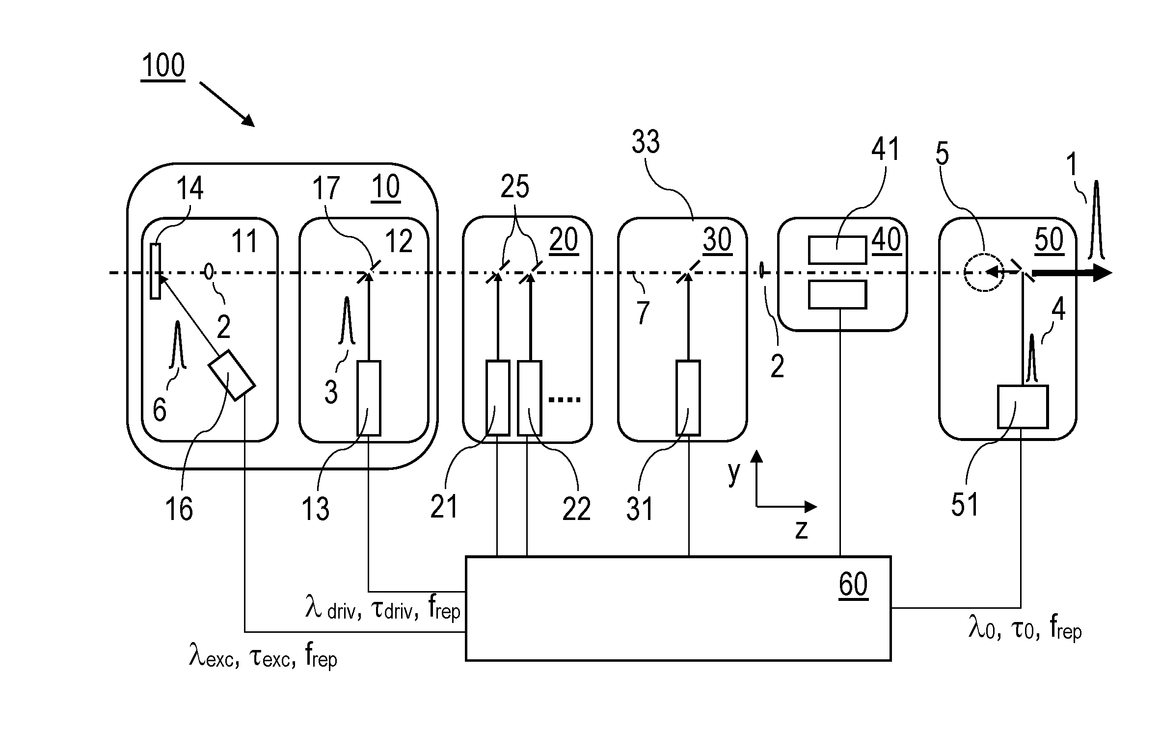
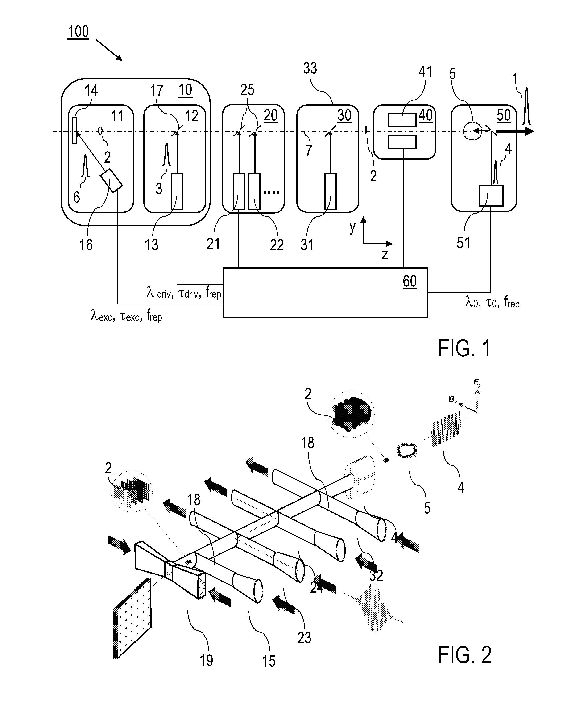
[0088]Features of preferred embodiments of the inventive X-ray source and the inventive method for creating X-ray pulses are described in the following with reference to FIGS. 1 and 2 showing the combination of an electron pulse source device including the THz driver pulse source for creating single cycle and multi-cycle THz driver pulses with the electromagnetic undulator. It is emphasized that details of the pulse sources for creating excitation pulses for the photoemission of the electrons, THz pulses for driving, accelerating and compressing purposes, and electromagnetic undulator pulses, as well as details of the inverse Compton scattering or FEL processes are not described as they are known as such from prior art. Furthermore, it is emphasized that the figures present schematic illustrations only. Details of the X-ray source, like sensor and monitoring equipment, vacuum equipment or enclosing vessels are not shown. The components of the X-ray source are illustrated as being co...


PUM


Abstract

X-ray pulse source (100) for generating X-ray pulses (1) includes electron pulse source device (10) including photo-emitter device (11) being configured for photo-induced creation of free electron pulses (2) and driver device (12) being configured for creating electromagnetic driver pulses (3) accelerating electron pulses (2) along acceleration path (7), and electromagnetic interaction device (50) comprising electromagnetic pulse source device (51) being configured for creating electromagnetic pulses (4) in interaction section (5) of electromagnetic interaction device (50), wherein electron pulse source device (10) and electromagnetic interaction device (50) are operable for generating X-ray pulses (1) by an interaction of electron pulses (2) and electromagnetic pulses (4), and driver device (12) includes THz driver pulse source (13), which is configured for creating single cycle or multi cycle THz driver pulses (3). Furthermore, a method of creating X-ray pulses (1) is described.

Description

BACKGROUND OF THE INVENTION[0001]The invention relates to an X-ray pulse source for generating X-ray pulses, in particular to an X-ray pulse source including an electromagnetic radiation based undulator. Furthermore, the invention relates to a method of creating X-ray pulses, in particular comprising the steps of photo-induced generating electron pulses, accelerating the electron pulses and creating the X-ray pulses by an interaction of the electron pulses and electromagnetic pulses. Applications of the invention are available in creating X-rays e. g. for imaging and / or investigation purposes, in particular for attosecond imaging and spectroscopy, for seeding an X-ray Free Electron Laser, for phase contrast imaging, X-ray crystallography and spectroscopy, lithography, X-ray scattering techniques, or ultrafast X-ray analysis.[0002]For describing the background of the invention, particular reference is made to the following publications:[0003][1] G. A. Krafft et al. in “Physical Revie...

Claims


Application Information

Patent Timeline
Patent Type & Authority Applications(United States)
IPC IPC(8): H05G2/00
CPCH05G2/008H05G2/00H05H9/02H05H2007/041H05H2007/027H01S3/0903
Inventor KAERTNER, FRANZ X.FALLAHI, ARYA
Owner DEUTES ELEKTRONEN SYNCHROTRON DESY
Why Eureka
Try Eureka