Embedded Turbofan Deicer System

Active Publication Date: 2016-12-01
JARVINEN PHILIP
View PDF7 Cites 21 Cited by
  • Summary
  • Abstract
  • Description
  • Claims
  • Application Information

AI Technical Summary

Benefits of technology

[0011]The present invention provides an embedded turbofan deicer system (ETDS) that prevents high altitude internal icing of turbofan engines operating near tropical storms. The ETDS particularly preventing icing occurring on internal turbofan parts including rotating engine spinner, fan blades, low pressure compr

Problems solved by technology

These internal ice deposits have effected engine operation detrimentally: causing loss of engine power and in some cases engine flameouts.
However, no understanding of the circumstances or the factors responsible for this type of internal icing is available.
A lack of knowledge regarding the upwelling weather in tropical convective storms is also hindering an understanding of the icing phenomena.
A number of theories as to the cause of high altitude turbofan engine internal icing have been offered with some theories lacking a sound basis because they do not take into account engine operation in proximity to a tropical convective storm and other theories suffering from a lack of detailed information about the process.
Though the engines quickly restarted and a safe landing was accomplished, the shutdown was subsequently attributed to ice deposits inside the jet engines: a situation never be

Method used


Image

  • Embedded Turbofan Deicer System
  • Embedded Turbofan Deicer System
  • Embedded Turbofan Deicer System

Examples


Embodiment Construction

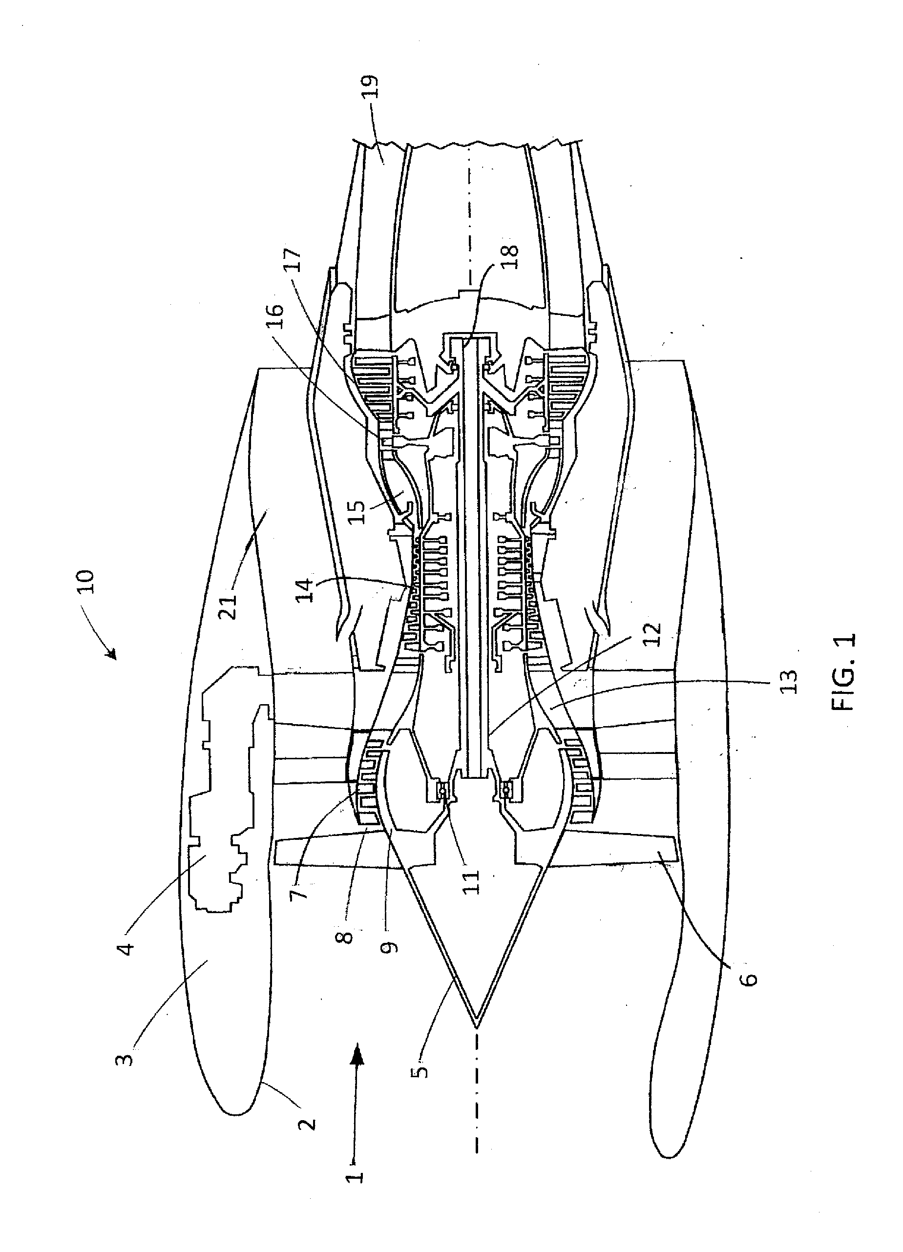
[0045]A cross-sectional diagram of a typical prior art turbofan aircraft engine of high bypass ratio 10 is provided in FIG. 1. Features of the typical prior art turbofan engine shown in FIG. 1, 10, starting at the inlet entrance and continuing to the exhaust end, include: inlet air flow, 1, inlet entrance duct, 2, nacelle, 3, aircraft / engine structural support, 4, engine spinner, 5, engine fan blades, 6, low pressure compressor, 7, low pressure compressor air inlet, 8, low pressure compressor casing, 9, forward bearing, 11, central drive shaft, 12, low pressure compressed air duct, 13, high pressure compressor, 14, combustion chamber, 15, high pressure turbine, 16, low pressure turbine, 17, aft bearing, 18, combustor exhaust duct, 19, and bypass air duct, 21. When icing is occurring inside a high bypass ratio turbofan engine at high altitudes near tropical storms, the ice attaches itself to internal exposed surfaces including the rotating engine spinner, 5, rotating engine fan blade...


PUM

PropertyMeasurementUnit
Pressureaaaaaaaaaa
Poweraaaaaaaaaa
Electrical conductoraaaaaaaaaa

Abstract

An embedded turbofan deicer system (ETDS) may eliminate the ingested ice crystal icing problem plaguing high bypass turbofan engines operating at high altitudes near convective tropical storms: icing occurring on the surfaces of the engine's rotating engine spinner, fan blades, low pressure compressor casing and low pressure compressor and causing loss of power and on occasion engine flameouts. The invention supplies electricity to heat these engine parts using at least one reversed permanent magnet electric generator (reversed PMEG) driven by the turbofan's central drive shaft with all parts of the ETDS mounted internal to the engine in presently unused internal spaces without requiring modifications to the existing engine. All electric power produced by the rotating reversed PMEG supplied directly to rotating engine parts requiring heat for deicing. A unique method to deice metal, composite and metal/composite fan blades is included in the invention using electricity from the reversed PMEG.

Description

CROSS REFERENCE TO RELATED APPLICATION[0001]This application claims benefit of U.S. Provisional Application Ser. No. 62 / 168,083, entitled, “Embedded Turbofan Deicer System” filed May 29, 2015, the entire disclosure of which is incorporated herein by reference.FIELD OF THE INVENTION[0002]The invention relates to the field of aircraft turbofan engine deicing devices. In particular to methods and devices used to prevent the build-up of ice internal to an aircraft's turbofan engine of high bypass ratio when operating at high altitudes typically above 30,000 feet; a recently encountered phenomenon. The ice caused by ice crystals existing in the atmosphere near tropical storms which are ingested into the engine. In the turbofan engine, the ingested ice crystals form ice that adheres to internal elements of the engine including rotating engine spinner, fan blades, low pressure compressor casing and low pressure compressor as well as air flow passages leading to the engine's combustion cham...

Claims


Application Information

Patent Timeline
IPC IPC(8): H05B3/12F01D15/10F01D25/02H05B3/16F04D29/32F04D29/38F01D21/00F02K3/06F04D29/52
CPCH05B3/12F02K3/06F01D15/10F01D25/02F04D29/522F05D2300/611F04D29/388F01D21/003H05B3/16F05D2220/36F05D2260/20F04D29/325F04D29/324F04D29/584F05D2220/768F02C7/047F05D2240/303H05B3/145H05B2203/013H05B2203/014H05B2214/02Y02T50/60F01D5/08
Inventor JARVINEN, PHILIP
Owner JARVINEN PHILIP
Why Eureka
Try Eureka