Motor driver of motor for valve timing control of internal combustion engine

a technology of internal combustion engine and motor driver, which is applied in the direction of electrical control, non-mechanical valves, electronic commutators, etc., can solve the problem of inability to achieve accurate motor rotation speed control with a sufficient responsiveness, and achieve accurate motor rotation speed control, improve motor control responsiveness, and improve the effect of such motor control

Active Publication Date: 2016-12-08
DENSO CORP
View PDF3 Cites 9 Cited by
  • Summary
  • Abstract
  • Description
  • Claims
  • Application Information

AI Technical Summary

Benefits of technology

[0006]It is an object of the present disclosure to provide a motor driver for a valve timing control motor in an electric VCT system of an internal combustion engine, which enables an accurate motor rotation speed control in a deceleration process or in a reverse rotation process of the motor in such system with an improved responsiveness of the motor control.
[0007]In an aspect of the present disclosure, the motor driver includes a motor drive unit driving a motor for a valve opening control of a valve by controlling a phase of a camshaft in an electric variable cam timing system. For driving such a motor drive unit, a motor rotation cycle obtainer obtains an actual rotation cycle of the motor, and a calculator calculates and outputs, to the motor dr

Problems solved by technology

Therefore, an accurate motor rotation speed control with a sufficient responsiveness is not achievable, based o

Method used


Image

  • Motor driver of motor for valve timing control of internal combustion engine
  • Motor driver of motor for valve timing control of internal combustion engine
  • Motor driver of motor for valve timing control of internal combustion engine

Examples


first embodiment

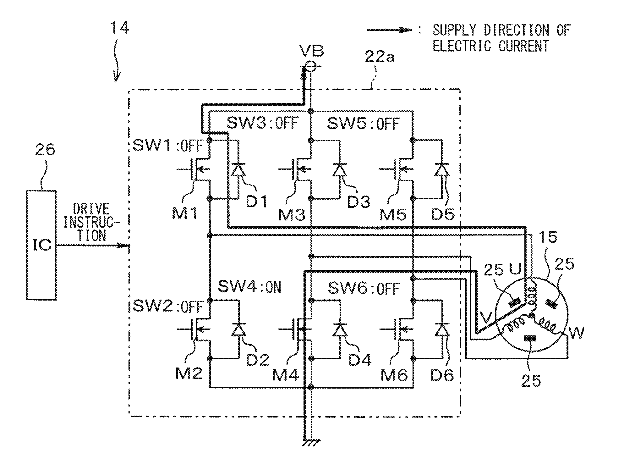
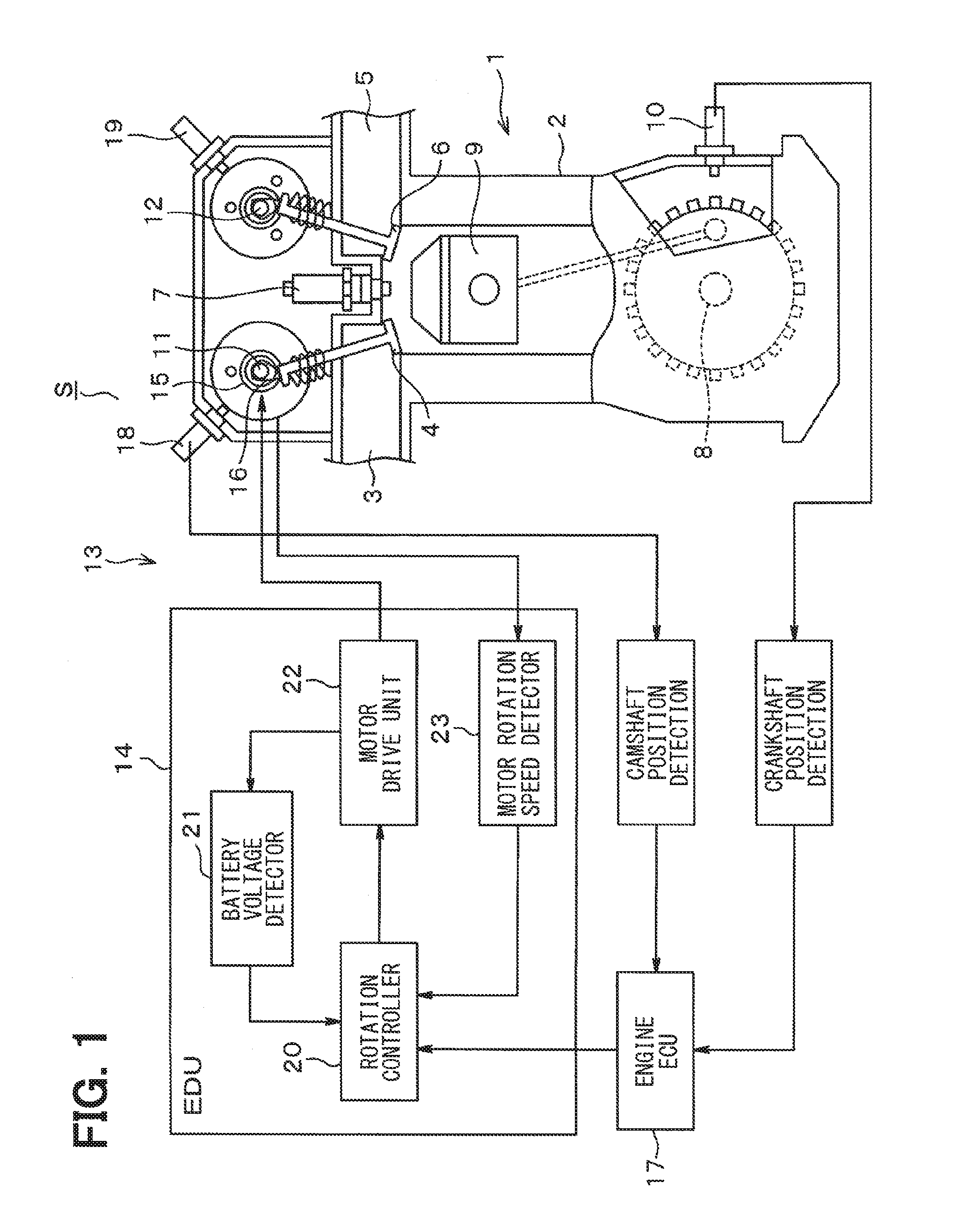
[0028]FIGS. 1 to 14 are used to illustrate the first embodiment of the present disclosure, about an electric variable cam timing (VCT) system S, in which a drive power of the cam timing system is derived from an electric motor. The electric VCT system is used to optimize a valve timing, i.e., a valve opening timing and a valve closing timing, for a reduction of exhaust emission, for a reduction of a pumping loss and a fuel mileage improvement, and for an increase of an engine output by the improvement of a suction / exhaust air efficiency.

[0029]In a body of an engine 1 that is provided as an internal-combustion engine, an engine block 2, an air intake passage 3, an air intake valve 4 disposed in the air intake passage 3, an exhaust passage 5, and an exhaust valve 6 disposed in the exhaust passage 5 are disposed as well as a spark plug 7 for ignition, a crankshaft 8, a piston 9 and the like.

[0030]A crank angle sensor 10 is installed on an outside of the crankshaft 8, and the crank angl...

second embodiment

[0159]FIGS. 15 to 17 show other diagrams relevant to the configuration of the second embodiment of the present disclosure.

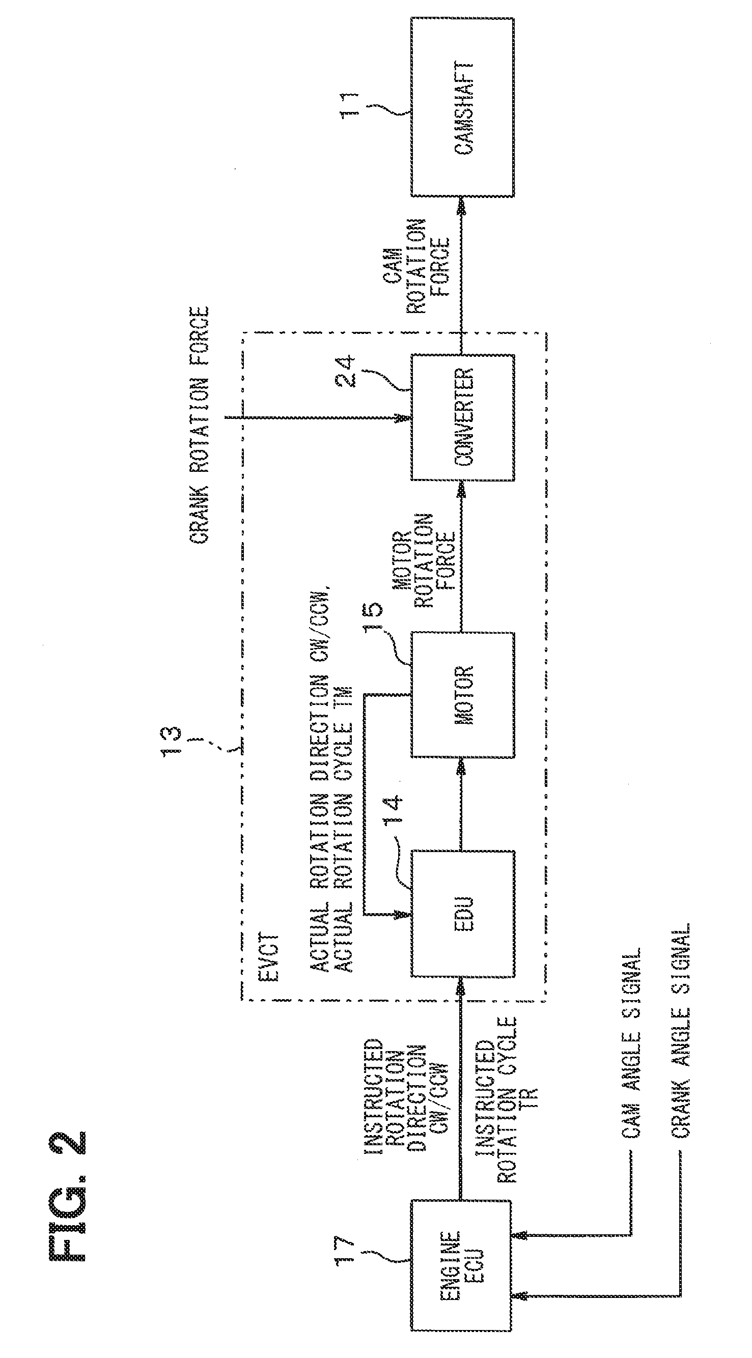
[0160]FIG. 15 is a block diagram of an electric VCT system S2 which replaces FIG. 1. The electric VCT system S2 is provided with a motor driver 113 for the valve timing control. The motor driver 113 for the valve timing control is provided with an EDU 114.

[0161]The EDU 114 includes a microcomputer, e.g., the IC 26, and other ICs, together with Random Access Memory (RAM), Read-Only Memory (ROM), and Electrically Eraseable Programmable Read-Only Memory (EEPROM), and provides various functions that serve as a rotation controller 120, which replace the rotation controller 20, the motor drive unit 22, and the motor rotation cycle detector 23.

[0162]The rotation controller 120 serves as a controller and a duty ratio corrector. Further, the rotation controller 120 is provided with a battery voltage detector 121. The battery voltage detector 121 primarily functions as a p...


PUM


Abstract

A motor driver for driving a motor in a valve timing controller of an internal combustion engine, including an Electronic Driver Unit (EDU) that, upon receiving a target rotation cycle as the instructed rotation cycle, instructs a rotation controller to (i) calculate a duty value of a Pulse Width Modulation (PWM) signal for driving the motor based on an instructed rotation cycle and an actual rotation cycle and (ii) output a calculation result of the duty value to a motor drive unit, with the rotation controller outputting, to the motor drive unit, an instruction signal that rotates the motor forward along an actual rotation direction, when the calculation result takes a positive value as a duty ratio of the PWM signal, establishing an accurate motor rotation speed control together with an improved responsiveness.

Description

CROSS REFERENCE TO RELATED APPLICATION[0001]The present application is based on and claims the benefit of priority of Japanese Patent Applications No. 2015-114799, filed on Jun. 5, 2015, and No. 2015-231736, filed on Nov. 27, 2015, the disclosure of which are incorporated herein by reference.TECHNICAL FIELD[0002]The present disclosure generally relates to a motor driver for driving a motor that controls a valve timing of an internal combustion engine.BACKGROUND INFORMATION[0003]An electric variable cam timing (VCT) system is developed as a device that optimizes, for example, a valve open / close timing of an air-intake value for supplying air to an engine and an exhaust valve for exhausting an exhaust gas from the engine, based on a variable and continuous control of a cam phase according to a state of driving of a vehicle, such as an engine rotation number, an accelerator opening, and the like, for the purpose of appropriate engine control and torque output.[0004]The prior art in the...

Claims


Application Information

Patent Timeline
IPC IPC(8): H02P6/08F01L9/04F01L1/34H02P27/08H02P6/14
CPCH02P6/08H02P27/08F01L9/04F01L1/34H02P6/14F01L1/344F01L3/20F01L2001/0537F01L2201/00F01L2250/02F01L2800/00F01L2820/032F01L2820/041F01L2820/042F02D2041/001F02D2041/2027H02P6/30F01L2013/103
Inventor NUMATA, TATSUHIROSATO, MASATAKE
Owner DENSO CORP
Why Eureka
Try Eureka