Optical decoder for thermal barcodes

an optical decoder and thermal barcode technology, applied in the field of optical decoders for thermal barcodes, can solve the problems of counterfeiting and unlawful use of objects, affecting the accuracy of thermal barcodes, so as to achieve high coding capacity, rapid heat up the taggant, and high capacity

Inactive Publication Date: 2016-12-22
NORTHEASTERN UNIV
View PDF1 Cites 2 Cited by
  • Summary
  • Abstract
  • Description
  • Claims
  • Application Information

AI Technical Summary

Benefits of technology

The present invention is a high capacity barcode system that uses nanoparticles for detection. The nanoparticles have unique melting peaks that can be detected optically. The system uses infrared light to quickly heat the taggant, and a thermal imager to capture the temperature changes during the heating and cooling process. This sudden and detectable change in temperature can identify the nanoparticles. The system is highly sensitive and can have a large coding capacity.

Problems solved by technology

Barcodes such as Universal Product Codes (UPC) are ubiquitously used to tag trading objects, but the visible barcodes can be altered or duplicated, facing increasing challenges such as product counterfeiting and unlawful use of objects (1).
However, existing taggants have various deficiencies.
Molecular or chemical taggants are not suitable for serialization due to the small coding space (4).
Graphical coding achieved by lithography is limited by structural integrity, material choice, and imaging identification (8,9).
Small sized nanoparticles have potential as covert barcodes, but the lack of nanoparticle-specific physical properties restricts their ability to label each object in a series.
Plasmonic nanoparticle enhanced Raman scattering has sharp peaks over a large wavelength range, but available Raman active dyes are limited, and quantitative signals are hard to obtain (12).
The method of reading nanoparticle-based barcodes relies on differential scanning calorimetry (DSC) analysis, which requires destructively sampling the taggant and placing the sample into a DSC pan, a process that is time consuming and cannot be performed remotely as with a common laser barcode scanner (21-24).

Method used


Image

  • Optical decoder for thermal barcodes
  • Optical decoder for thermal barcodes
  • Optical decoder for thermal barcodes

Examples


example 1

Characterization of Nanoparticles Using Their Melting Temperature

[0037]Stearic acid, palmitic acid, lauric acid and icosane were obtained with melting temperatures of 69.3, 62.9, 43-45, and 36-38° C., respectively. 10-20 mg of samples were placed in an aluminum alloy sample disk and heated with a radiant infrared electric heater (IR30S) and cooled down to room temperature. An infrared camera (FLIR T430sc) was used to record the temperature change of the thermal barcode during heating and cooling processes. A differential scanning calorimeter (PerkinElmer DSC7) was used to measure the thermal properties of materials at thermal ramp rate 10° C. / min within the range of 25 to 90° C. The cooling rate was controlled to be at 10° C. / min within the range of 90 to 0° C. by using a water cooling unit. The infrared camera was connected to a computer via a data line, and an FLIR tools+ software was used to record and analysis the data collected from barcodes.

[0038]FIGS. 2A-2F show thermal image...

example 2

Characterization of Nanoparticles Using Their Solidifying Temperature

[0040]A similar strategy was used to identify the freezing point of each sample from Example 1. These were determined to be 67.7, 61.5, 43.0 and 35.8° C. for stearic acid, palmitic acid, lauric acid and icosane, respectively. The measured freezing points are in the same range of the reported melting points, which indicated no supercooling occurs throughout thermal imaging. The lack of supercooling is likely due to edge effect of slot, which facilitates the heterogeneous nucleation. In comparison, the freezing points of the four materials (FIG. 3D) by DSC were several to tens of degrees lower than the ones measured through infrared camera. The difference is probably caused by supercooling, which is due to lack of nucleation site in smooth aluminum pans. The decreases in freezing points were 8.5, 10.1 and 11.9° C. for stearic acid, palmitic acid and lauric acid, respectively. No freezing peak was observed in the case...

example 3

Manufacturing and Use of Covert Taggant

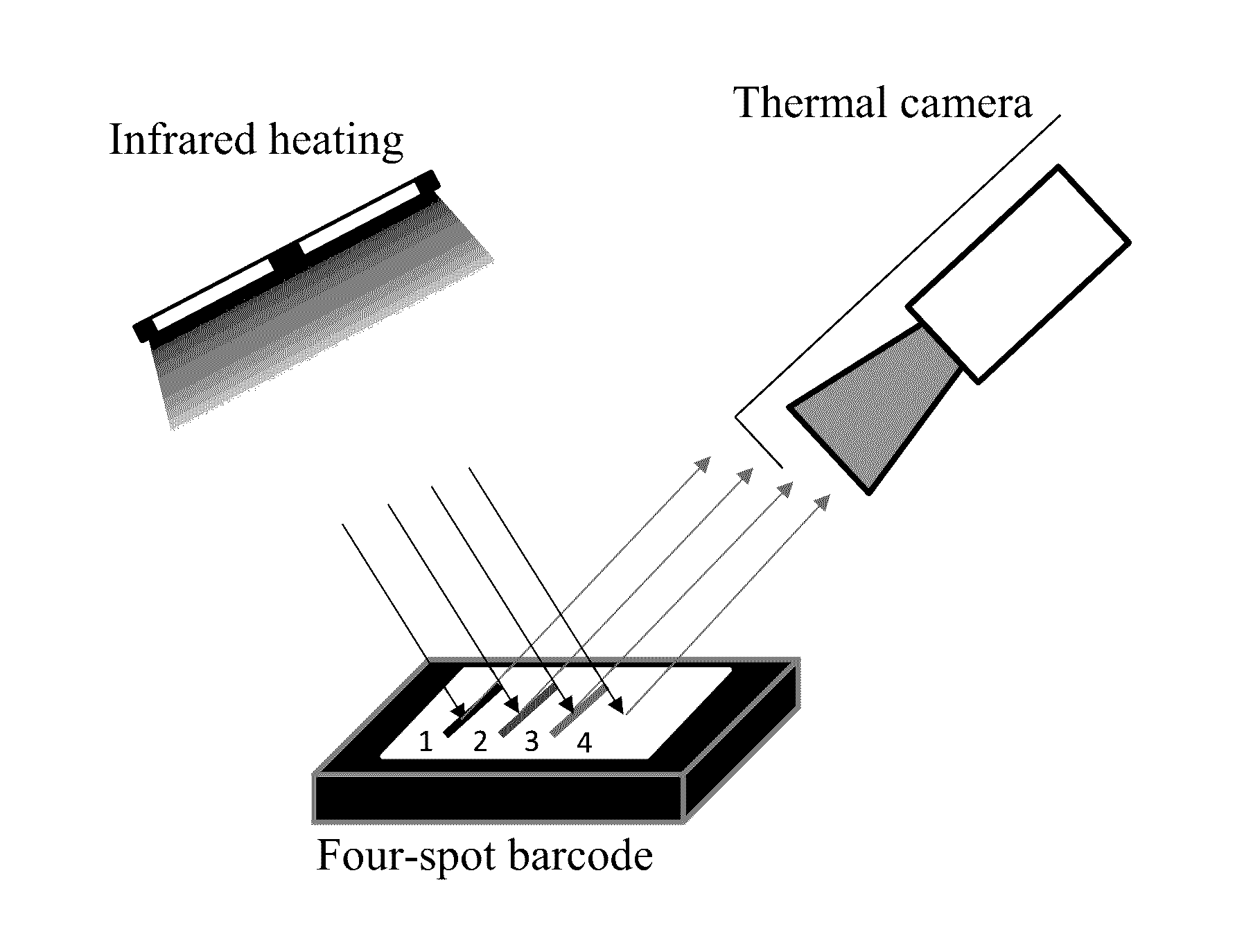
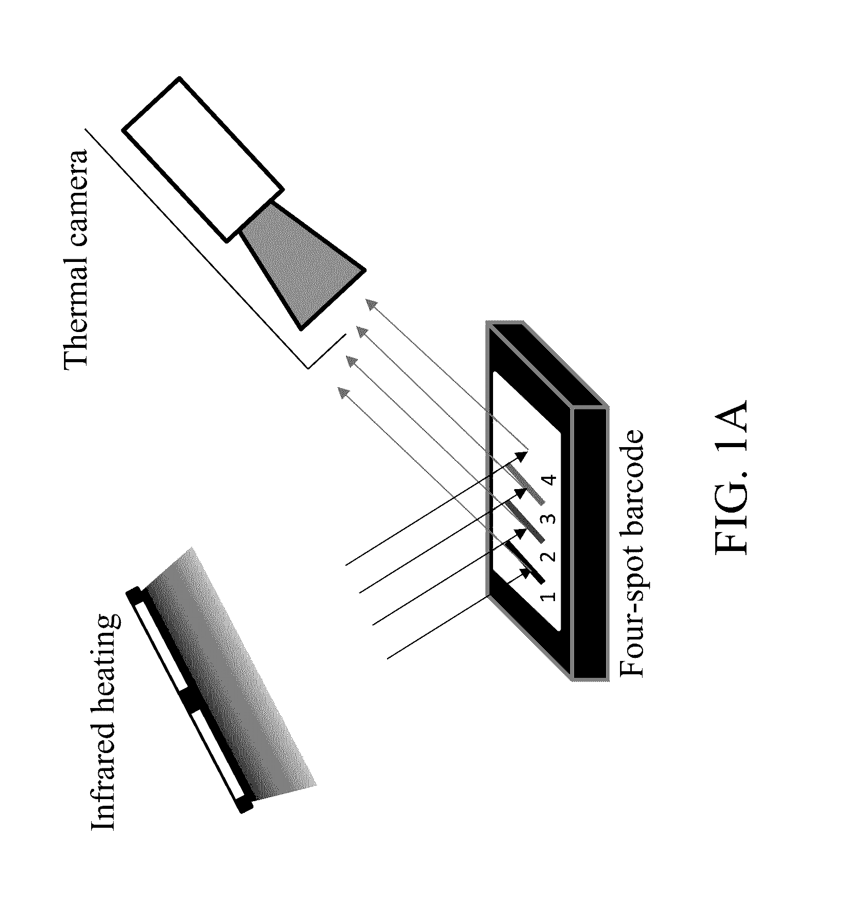
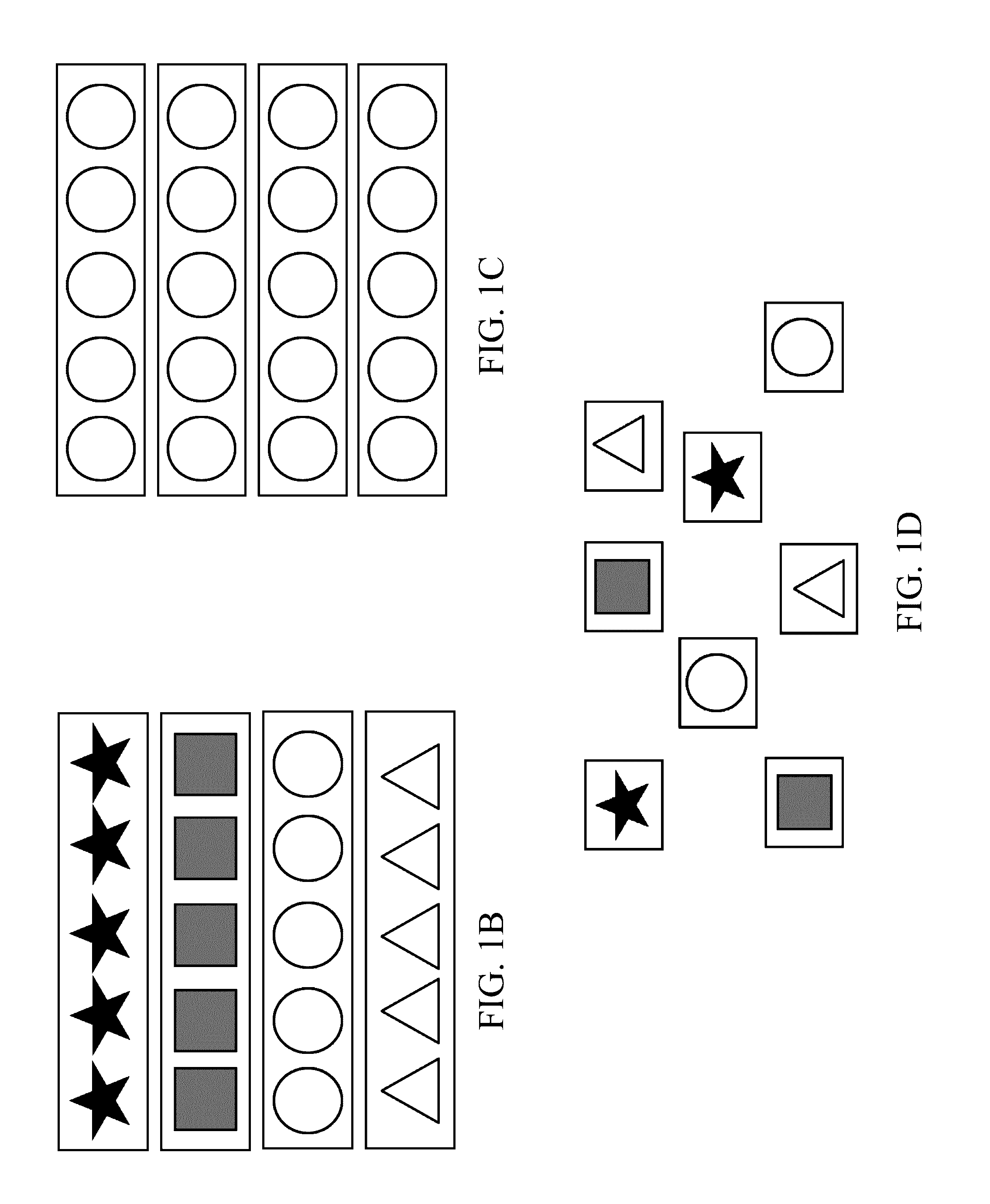
[0041]Selected PCMs (3-5 mg) were placed on a piece of printing paper in four locations. Each location contained one of the four PCMs (FIG. 1A). The total number of possible arrangements was 44=256 based on the different combinations of printing locations and PCMs. Each barcode consisted of four sequential letters, where S stands for stearic acid, P stands for palmitic acid, L stands for lauric acid, and I stands for icosane. The paper was heated with an infrared source and recorded by the infrared camera. Data extracted with FLIR tools+ is shown in the upper three pictures in Figure FIGS. 5A-5C. Lines 1 to 4 stand for the temperature increasing curves of the PCMs at location 1 to 4. The rates of temperature change curves are shown in the lower three graphs. In the first barcode, the sequence of the four PCMs is stearic acid, palmitic acid, lauric acid and then icosane, forming the barcode SPLI. Similarly, the second and third barcodes are LIPS...


PUM

PropertyMeasurementUnit
thermodynamically critical diameteraaaaaaaaaa
temperaturesaaaaaaaaaa

Abstract

A high capacity nanoparticle-based covert barcode system relies on an entirely optical readout for detection. The system includes a panel of phase change nanoparticles with sharp and discrete melting peaks; readout is based on heating with an infrared source and detection using an infrared imager, and detection of their phase transition temperatures and positions. A readily detectable and sudden change in temperature occurs at the phase transition during a heating or cooling process, and can be used to indicate the identity of nanoparticles.

Description

CROSS REFERENCE TO RELATED APPLICATIONS[0001]This application claims the priority of U.S. Provisional Application No. 62 / 308,978 filed Mar. 16, 2016 and entitled “Optical Decoder for Thermal Barcodes”; and claims priority to U.S. Provisional Application No. 62 / 180,770 filed Jun. 17, 2015 and entitled “All-Optical Thermal Barcode Reader”. Both of said provisional applications are hereby incorporated by reference in their entireties.STATEMENT REGARDING FEDERALLY SPONSORED RESEARCH OR DEVELOPMENT[0002]This invention was developed with financial support from Grant Number 105599 from the National Science Foundation, and Grant Number 2012-DN-BX-K021 from the United States Department of Justice. The U.S. Government has certain rights in the inventionBACKGROUND[0003]Barcodes such as Universal Product Codes (UPC) are ubiquitously used to tag trading objects, but the visible barcodes can be altered or duplicated, facing increasing challenges such as product counterfeiting and unlawful use of ...

Claims


Application Information

Patent Timeline
Patent Type & Authority Applications(United States)
IPC IPC(8): G06K7/14G06K19/06G01N21/35
CPCG06K7/1413G06K19/0615G01N21/35G01N25/02G06K19/06178G06K7/10722G06K7/12G06K19/06018G06K19/06028G06K19/06084G06K19/0614G01N25/00
Inventor SU, MINGHOU, SICHAOWANG, MIAO
Owner NORTHEASTERN UNIV
Why Eureka
Try Eureka