Pure oxygen direct combustion system using liquid metal

a technology of pure oxygen and direct combustion, which is applied in the direction of lighting and heating apparatus, furnaces, charge manipulation, etc., can solve the problems of difficult flame adjustment, high cost of concentrating low-concentration dioxide in the flue gas, and heat loss, so as to reduce the load of a purification facility, the effect of overloading the reactor and high boiling poin

Active Publication Date: 2017-01-05
KOREA INST OF IND TECH
View PDF16 Cites 3 Cited by
  • Summary
  • Abstract
  • Description
  • Claims
  • Application Information

AI Technical Summary

Benefits of technology

[0021]As described above, in the pure oxygen direct combustion system using a liquid metal according to the present invention, because sensible heat of high temperature generated in a pure oxygen combustion reaction process of a solid fuel is provided to a metal in the reactor to be used in a metal liquefying process and is circulated and supplied and heat is exchanged in a process of circulating a liquid metal of high temperature, an overload of the reactor can be reduced in the process of supplying the liquid metal of a middle / low temperature into the reactor again.
[0022]According to the present invention, an effect of reducing a load of a purification facility disposed at a rear side of the system through a process of separating impurities and unburned powder contained in the gases from the gases by injecting the liquid metal to the gases using nozzles.
[0023]According to the present invention, an effect of eliminating impurities contained in gases by injecting the liquid metal to the gases using nozzles.
[0024]Further, because the liquid metal used in the present invention is melted at an operation range to maintain a liquid state and has a high boiling point, loss due to evaporation thereof can be prevented.
[0025]Further, because the liquid metal used in the present invention has a high thermal capacity as compared with air and water mainly used for the existing heat exchange, the heat transfer efficiency is high so that heat can be effectively exchanged and the liquid metal can be moved conveniently due to its low viscosity.
[0026]Further, the liquid metal used in the present invention makes direct contact with gases, which are to be heated, to exchange heat, and can easily control heat exchange efficiency through changing a spray condition of the liquid metal.

Problems solved by technology

Meanwhile, because a considerable amount of calories generated when air is burned is used to heat nitrogen, heat loss is caused, and because the concentration of carbon dioxide in the flue gas is as low as 20% or less, considerable costs are consumed to concentrate dioxide of low concentration in the flue gas to a high concentration.
If oxygen is used as an oxidizer, it is difficult to adjust flames because a rapid exothermic reaction is caused when the oxidizer makes contact with a fuel as compared with the case in which air is used as an oxidizer.
That is, in general, while the pure oxygen direction combustion has a good thermal efficiency and discharges a small amount of atmospheric contaminants, it produces combustion gases of high temperature of 3000 degrees or higher so that it is difficult to apply the method to a heat exchanger.
However, the cited documents disclose only that parts of waste steam or flue gases discharged from a combustion unit are heat exchanged and supply water is preheated and vapor is reheated for heat exchange through recirculation of combustion gases, and fail to disclose a pure oxygen direct combustion apparatus that does not accompany recirculation of combustion gases.

Method used


Image

  • Pure oxygen direct combustion system using liquid metal
  • Pure oxygen direct combustion system using liquid metal
  • Pure oxygen direct combustion system using liquid metal

Examples


first embodiment

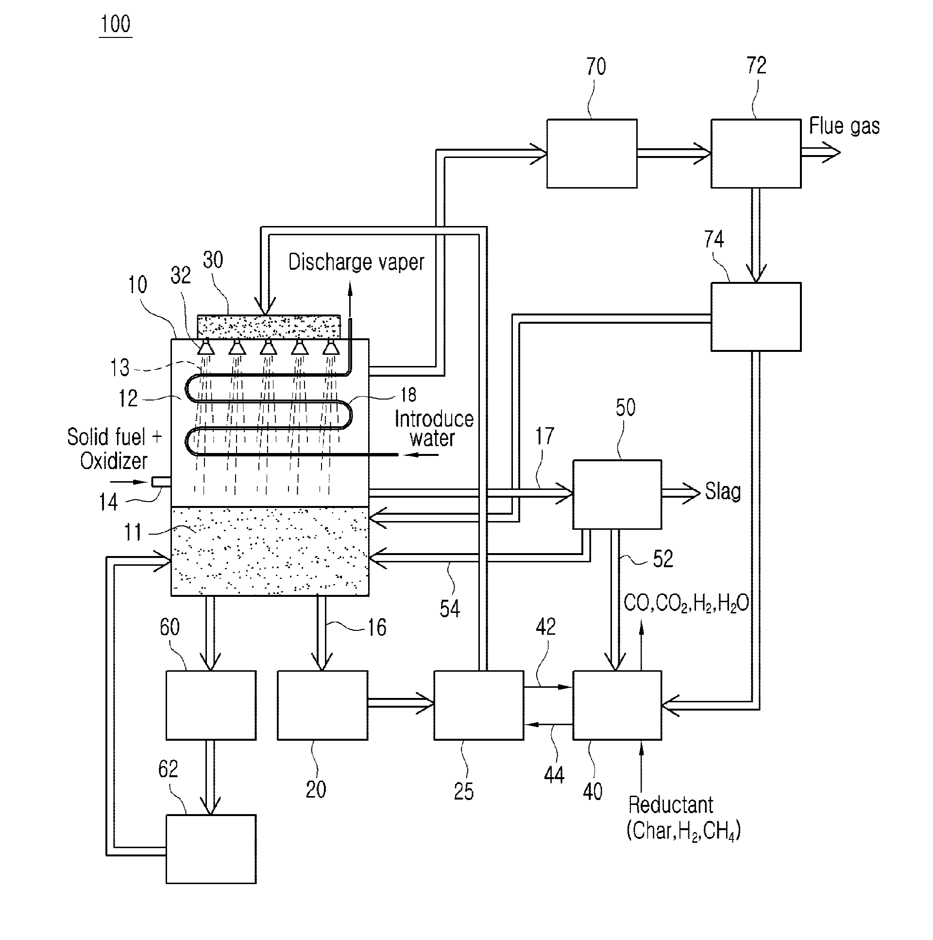
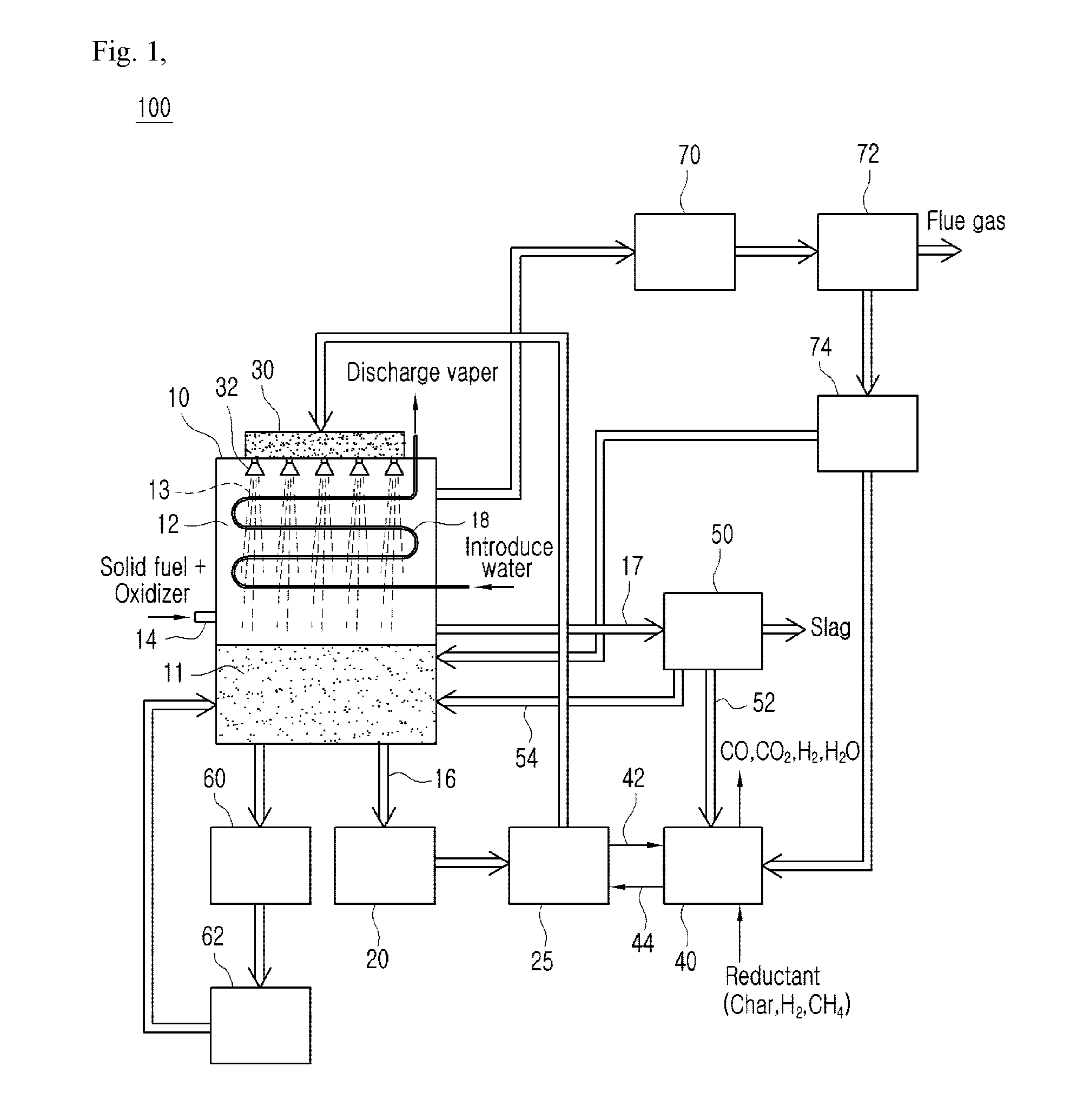
[0035]Hereinafter, a configuration of the pure oxygen direct combustion system 100 using a liquid metal according to the present invention will be described with reference to FIG. 1.

[0036]The pure oxygen direct combustion system 100 according to the present invention includes a reactor 10 to which an oxidizer and a fuel are supplied such that a combustion process is performed, a first heat exchanger 20 connected to a lower portion of the reactor 10 such that heat is exchanged between a liquid metal 11 and the first heat exchanger 20, a circulation pump 25 connected to a rear end of the heat exchanger 20 to circulate the liquid metal 11, a buffer tank 30 connected to the circulation pump 20 and situated on the upper surface of the reactor 10, a plurality of nozzles 32 coupled to the lower surface of the buffer tank 30 and having a plurality of injection holes through which the liquid metal 11 of the buffer tank 30 is injected into the reactor 10, a reduction unit 40 connected to the ...

second embodiment

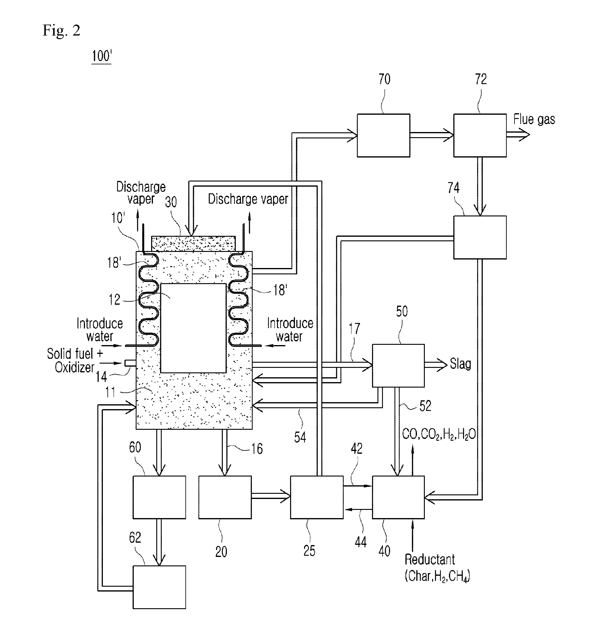
[0058]Hereinafter, a configuration of the pure oxygen direct combustion system 100 using a liquid metal according to the present invention will be described with reference to FIG. 2.

[0059]In the second embodiment 100′, the same parts as the first embodiment 100 will be omitted and different technical parts will be mainly described.

[0060]The pure oxygen direct combustion system 100′ is configured such that a liquid metal 11 surrounds a space in which a combustion gas 12 in a reactor 10′ is generated. The liquid metal 11 may be supplied through an upper portion of the reactor 10′ from a buffer tank 30 without using a separate nozzle while the nozzles 32 in the first embodiment 100 are removed. The water flow pipe 18′ is disposed on a wall surface of the reactor 10′ and makes contact with the liquid metal 11 that flows down along the wall surface. Through the above-mentioned structure, overheating and slagging of the water flow pipe 18′ can be prevented. Through this, a high temperatur...


PUM


Abstract

A pure oxygen direct combustion system using a liquid metal according to the present invention comprises: a reactor for receiving a liquid metal; a heat exchanger, connected to the bottom of the reactor, for exchanging heat for the liquid metal; a circulation pump, connected to the heat exchanger, for circulating the incoming liquid metal; a nozzle, connected to the circulation pump and disposed on the reactor; a reduction unit, connected to the circulation pump, for performing a reduction for the oxidized liquid metal; and a separation unit, connected to the reactor and the reduction unit, wherein the particles of the liquid metal injected from the nozzle are subjected to sensible heat from the gas generated from the reactor, heat-exchanged by the heat exchanger and regenerated by the reduction unit, and then supplied back to the reactor.

Description

TECHNICAL FIELD[0001]The present invention relates to a pure oxygen direct combustion system using a liquid metal, and more particularly to a pure oxygen direct combustion system using a liquid metal that supplies only oxygen to a solid fuel such as coal to burn the solid fuel, and reduces the load of a heat exchanger which is a disadvantage of a conventional system and maximizes thermal efficiency by using a flow process of the liquid metal that uses a heat source of high temperature generated when the pure oxygen is burned as a layer material and a heat transfer medium.BACKGROUND OF THE DISCLOSURE[0002]In general, it is known that about 54% of carbon dioxide generated in the industry is discharged in thermal power plants. Because carbon dioxide is a gas that is generally generated in the process of burning fuels, the amount of discharged carbon dioxide should be reduced at a fuel combustion time point.[0003]The existing thermal power plants use an air combustion method in which ai...

Claims


Application Information

Patent Timeline
Patent Type & Authority Applications(United States)
IPC IPC(8): F23L7/00F23J15/02F27D7/02F27D17/00F27D3/14
CPCF23C99/00F23L7/007F27D3/14F27D7/02F27D17/004Y02E20/34F23L7/00F27D17/00F23J15/02F23L7/005
Inventor LEE, UEN DOYANG, WONMOON, JI HONG
Owner KOREA INST OF IND TECH
Why Eureka
Try Eureka