In-Line Composition and Volumetric Analysis of Vent Gases and Flooding of the Annular Space of Flexible Pipe

a flexible pipe and vent gas technology, applied in the field of pipe structure monitoring, can solve the problems of infrequent and high cost for operators, corrosion and/or corrosion-fatigue type failure of the pipe structure, time-consuming process, etc., and achieve the effect of reducing the number of incidents and increasing the frequency of inspections

Inactive Publication Date: 2017-01-26
SCHLUMBERGER TECH CORP
View PDF0 Cites 11 Cited by
  • Summary
  • Abstract
  • Description
  • Claims
  • Application Information

AI Technical Summary

Benefits of technology

[0006]The present invention includes the recognition that the methods and techniques commonly used in the industry for monitoring flexible pipe structures are time consuming and require the production of hydrocarbons to be partially or totally stopped. Because of the time inherent in these operations, they are performed infrequently and at great expense to the operators. This is the main driver to find innovative ways to permanently monitor the integrity of pipe's structures that are less intrusive resulting in an increase of the frequency of inspection to ultimately reduce the number of incidents.
[0009]A second exemplary embodiment of the present invention that can be optionally combined with the first exemplary embodiment, includes novel techniques for determining the presence of water or liquids in the annulus of a flexible pipe, e.g., flexible riser or flowline in a subsea system using information on the annulus gas vent rate and pressure. The presence of such water / liquid in the annulus can result from, for example, condensation in the annulus, slow intrusion of liquid from the inside or outside of the flexible pipe through the protective layers or break-down of an outer sheath of the flexible pipe, resulting in flooding of the annulus Advantageously, information on variations of temperature in the riser annulus also can be provided. In an exemplary aspect, a device, including a pressure transducer together with a volumetric or mass flow meter, is placed in-line with the annulus vent port of a flexible riser. The device can be used to collect pressure, temperature and flow information during the gas annular venting event. In a further aspect, the device is located inside the end-fitting or before the annulus venting check valve (which may also be referred to herein as “vent-check valve” or “vent gas valve”), enabling the recording and interpretation data not only during the venting, but also during the build-up of the annular pressure. As pressures builds inside the annulus, it eventually reaches the pressure by which the vent check-valve in the end-fitting opens, resulting in gas being vented out of the annulus. A state-of the art vent check-valve includes a mechanical spring with a face seal remaining open until the pressure decreases to a pre-determined value at which time the valve closes and the annular pressure starts building again due to the constant but slow process of diffusion through the flexible pipe, e.g., flexible riser pressure sheath. During the initial venting period, the vented gas flow rate is typically significantly larger than the diffusion rate and dominates the pressure drop in the annulus space. The interpretation of the pressure drop and flow rate enables the determination of the total gas volume present in the annular space. If the diffusion rate is such that the vent check-valve does not generate sufficient flow rate during the initial stages of the venting sequence, a piloted valve can be used to increase the flow port opening and resulting flow rate. The later part of the draw-down and the build-up can be used to determine the diffusion rate of the particular riser.
[0010]The ability to accurately measure the total volume without the need to use a positive displacement meter advantageously is provided. Due to various vent system implementations, there is a wide range of flow rates that a meter must accurately cover, leading to the current practice of a positive displacement measurement system. However, this incurs additional maintenance and reduced service life due to the dynamic seals in the pistons. Accordingly, in a further aspect a flow meter can be employed with non-moving parts (e.g., an intrusive acoustic flow meter) with an additional valve to shut-off the flow when the flow rates cross a threshold below which the accuracy of the meter would be degraded. A further aspect replaces the vent check-valve by an actuated valve, enabling better control of the flowing rates and pressures to maximize the accuracy of the interpretation results. The ability to control the venting operation also enables a more efficient sample collection, whenever it is deemed necessary. Advantageously, variations in the temperature of the annulus can also be detected. The exemplary embodiments also can be used with compressed air or any other gas, added to the annulus, in case the diffusion rate of gas through the inner sheath of the flexible riser is too low to make frequent measurements. The exemplary embodiments also include the use of only one system to monitor multiple flexible pipes or risers.

Problems solved by technology

Because of the time inherent in these operations, they are performed infrequently and at great expense to the operators.
The repercussions of the above mentioned failure incidents could result in corrosion and / or corrosion-fatigue type failure of the pipe structure.
However, as noted above, this is a time consuming process.

Method used


Image

  • In-Line Composition and Volumetric Analysis of Vent Gases and Flooding of the Annular Space of Flexible Pipe
  • In-Line Composition and Volumetric Analysis of Vent Gases and Flooding of the Annular Space of Flexible Pipe
  • In-Line Composition and Volumetric Analysis of Vent Gases and Flooding of the Annular Space of Flexible Pipe

Examples


first embodiment

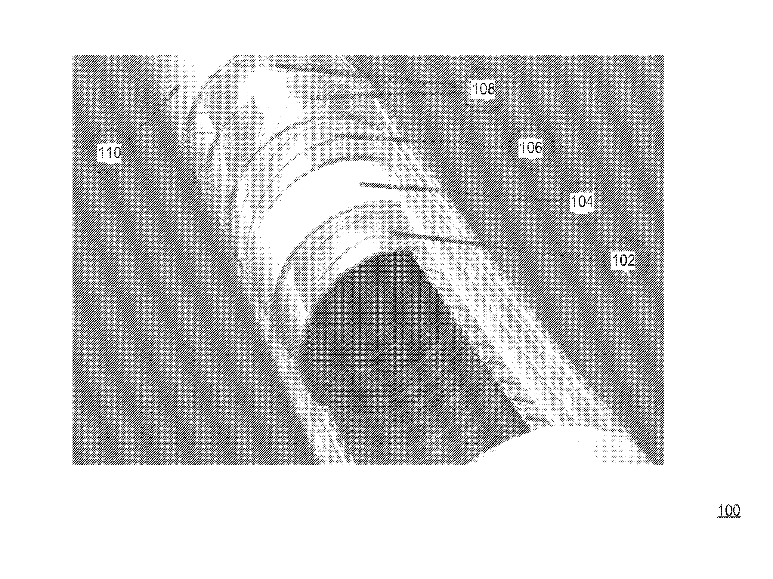
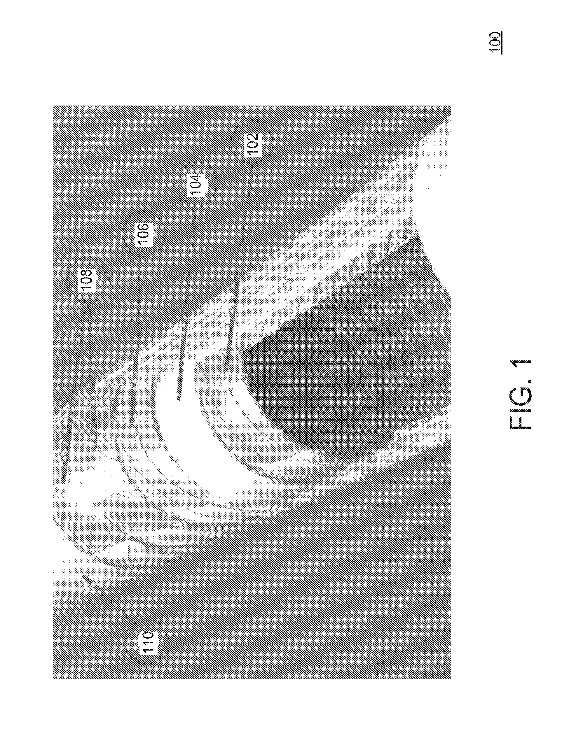
[0031]Referring now to the drawings, wherein like reference numerals designate identical or corresponding parts throughout the several views, and more particularly to FIG. 1 thereof, there is illustrated a flexible pipe structure 100 which includes a carcass layer 102 (which may also be referred to as “carcass 102”) that is designed to keep the pipe 100 from collapsing to the external pressure to which the pipe 100 is subjected and is in permanent contact with the produced fluid. The carcass layer 102 is usually manufactured from a corrosion resistant material. A pressure sheath 104 (which may also be referred to as “inner sheath 104” or “inner liner 104”) is a polymer layer that is provided and designed to act as a pressure barrier keeping the produced fluids in the flexible pipe 100. A failure of the pressure sheath 104, for example, due to cracks and fissures, and the like, might allow fluid to enter the annulus and although it is designed to be impermeable to fluid, with time ga...

second embodiment

[0051]The present invention includes recognition that flexible pipes or risers have some drawbacks. Referring again to FIG. 1, the typical flexible pipe or riser structure 100 includes the many layers, each of which plays a different role from providing structural strength to providing isolation between the inside bore, which carries producing fluids, from the outside sea water. The steel reinforcing layers (armors 108 and pressure vault layer 106) are contained within a very confined environment called the annulus which is located between the inner polymer sheath 104 and the external polymer sheath 110. The inner sheath 104 is the barrier to the conveyed production fluids and the external sheath 110 protects against the seawater environment. If this annulus has water present in it, then the longer term integrity of the flexible riser 100 is compromised because of corrosion. It should be noted that although the inner 104 and outer sheaths 110 are impermeable, under high temperature ...


PUM


Abstract

A method and system for monitoring a flexible pipe, including an inline sensor system coupled to the annulus of the flexible pipe to detect corrosion of the flexible pipe. Also disclosed are method and system for monitoring an amount of water being accumulated in an annulus of a flexible pipe, including locating a pressure measurement system proximate to the annulus for measuring pressure of gas inside the annulus; controlling a flow of vent gas with a vent gas valve; positioning a flow measurement system upstream or downstream of the vent gas valve for measuring the flow of the vent gas when the vent gas valve is opened; and collecting with a microprocessor pressure and flow measurement data from the pressure and the flow measurement systems for determining the amount of water accumulated in the annulus based on the collected pressure and flow measurement data.

Description

BACKGROUND OF THE INVENTION[0001]Field of the Invention[0002]The present invention generally relates to the monitoring of pipe structures, and more particularly to a system and method for composition and volumetric analysis of vent gasses and detection of water flooding in an annular space of a flexible pipe structure.[0003]Discussion of the Background[0004]The monitoring of pipe structures is of great importance in many areas, in particular in the oil and gas industry, even more important in subsea environment where access to the structures is difficult. As an example, a pipeline running at the sea bed between an offshore production location to a transportation hub may need to be monitored to provide information regarding its integrity. Subsea production is growing in importance for many oil companies and is projected to increase significantly in the next 5-10 years. In addition, offshore fields are being exploited in deeper and deeper waters. However, producing from floating produ...

Claims


Application Information

Patent Timeline
Patent Type & Authority Applications(United States)
IPC IPC(8): G01M3/28
CPCG01M3/2815E21B47/1025G01N17/04G01F1/00E21B47/07E21B47/117E21B49/0875E21B17/01E21B34/00E21B47/06E21B49/08G01F1/68G01F1/84G01N1/10G01N30/02G01N33/004G01N33/0044G01N35/0092
Inventor MANGAL, LARS NICOLASVANNUFFELEN, STEPHANERAMOS, ROGERIO TADEUVASQUES, RICARDO R.BERARD, MICHEL V.DION, DOMINIQUE
Owner SCHLUMBERGER TECH CORP
Why Eureka
Try Eureka