Right Angle Time-of-Flight Detector With An Extended Life Time

a detector and right angle technology, applied in mass spectrometers, particle separator tube details, radiation intensity measurement, etc., can solve the problems of significantly limiting factors of detector life, reducing life time to under one coulomb, etc., to suppress slow fluorescence, enhance detector efficiency, and excellent detection efficiency of individual ions

Active Publication Date: 2017-01-26
LECO CORPORATION
View PDF8 Cites 27 Cited by
  • Summary
  • Abstract
  • Description
  • Claims
  • Application Information

AI Technical Summary

Benefits of technology

[0015]This disclosure describes experimental tests of the proposed detector which confirmed: extended life time; excellent detection efficiency of individual ions; fast time response; immunity to noise and pulse signals; and practical convenience of detector mounting and replacement.
[0016]In another embodiment, for TOF MS applications with a limited ionic flux, there are proposed a version of the above described detector with an additional SEM or MCP stage and a method for suppressing slow fluorescence by setting amplification between primary ions and primary PMT electrons above 10-times and setting a threshold for suppressing individual photons produced by slow fluorescence. The proposed detector employs multiple other means proposed to enhance detector efficiency to minimize MCP amplification and, thus, extending life time of the hybrid detector. There are also proposed several convenient designs for flexible changes between detector sets, including right angle steering of secondary electrons past the MCP.

Problems solved by technology

Thus, detector life time presents a significantly limiting factor.
However, when placed in a technical vacuum (occurring in TOF MS when SEM is not sealed), those active surfaces contaminate and deplete oxides, thus reducing life time to under one Coulomb (1 C).
The converter 18 does not solve the main problem of prior art TOF detectors (i.e. small dynamic range and short life time).
However, the MCP stage 14 may limit both dynamic range and life time.
Finally, poor photon coupling requires strong MCP amplification, further aggregating the above negative effects.
Existing TOF detectors fail to satisfy multiple conditions for these fluxes.
For example, they have a very limited dynamic range.
And they have too short of a life time.
Higher biasing (up to +10 kV) is preferred for higher signal gain, but may be limited for practical reasons (for example, by the available space and insulation).
However, such improvements may be insufficient for handling temporal peak signals.
Those two features strongly limit both the life time and the dynamic range of the detector 22.
Besides, partially destroyed coating causes poorly controlled energy loss of secondary electrons and sweet spots on the hybrid detector 22.
Without this optimization, the MCP omission would reduce the ion detection probability and would not be suitable for detecting individual ions.
Referring to FIG. 9, if the magnets are shifted from the optimal position, Y-directional electron defocusing occurs and causes additional time aberrations and spatial losses.

Method used


Image

  • Right Angle Time-of-Flight Detector With An Extended Life Time
  • Right Angle Time-of-Flight Detector With An Extended Life Time
  • Right Angle Time-of-Flight Detector With An Extended Life Time

Examples


embodiment

[0057]Detector Embodiment

[0058]To alleviate the above described problems, the detector's dynamic range and life time have been enhanced and adopted for a multi-reflecting TOF MS (MR-TOF MS) in the following novel combination.

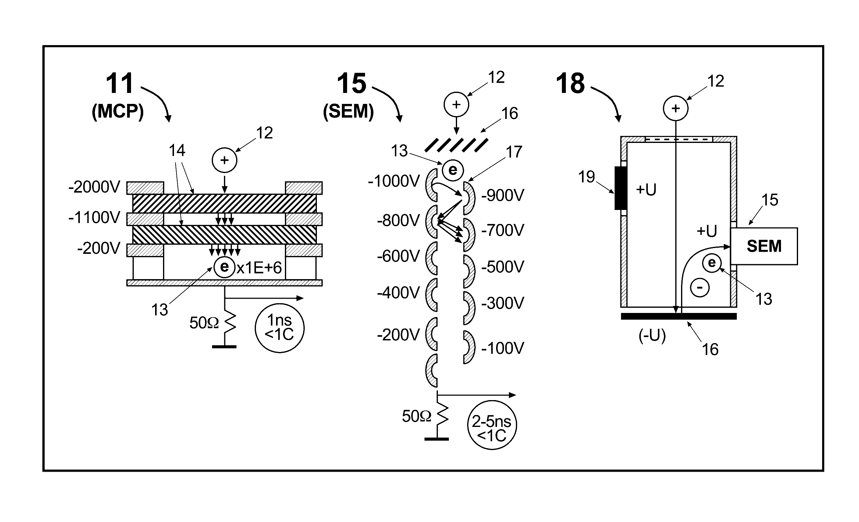
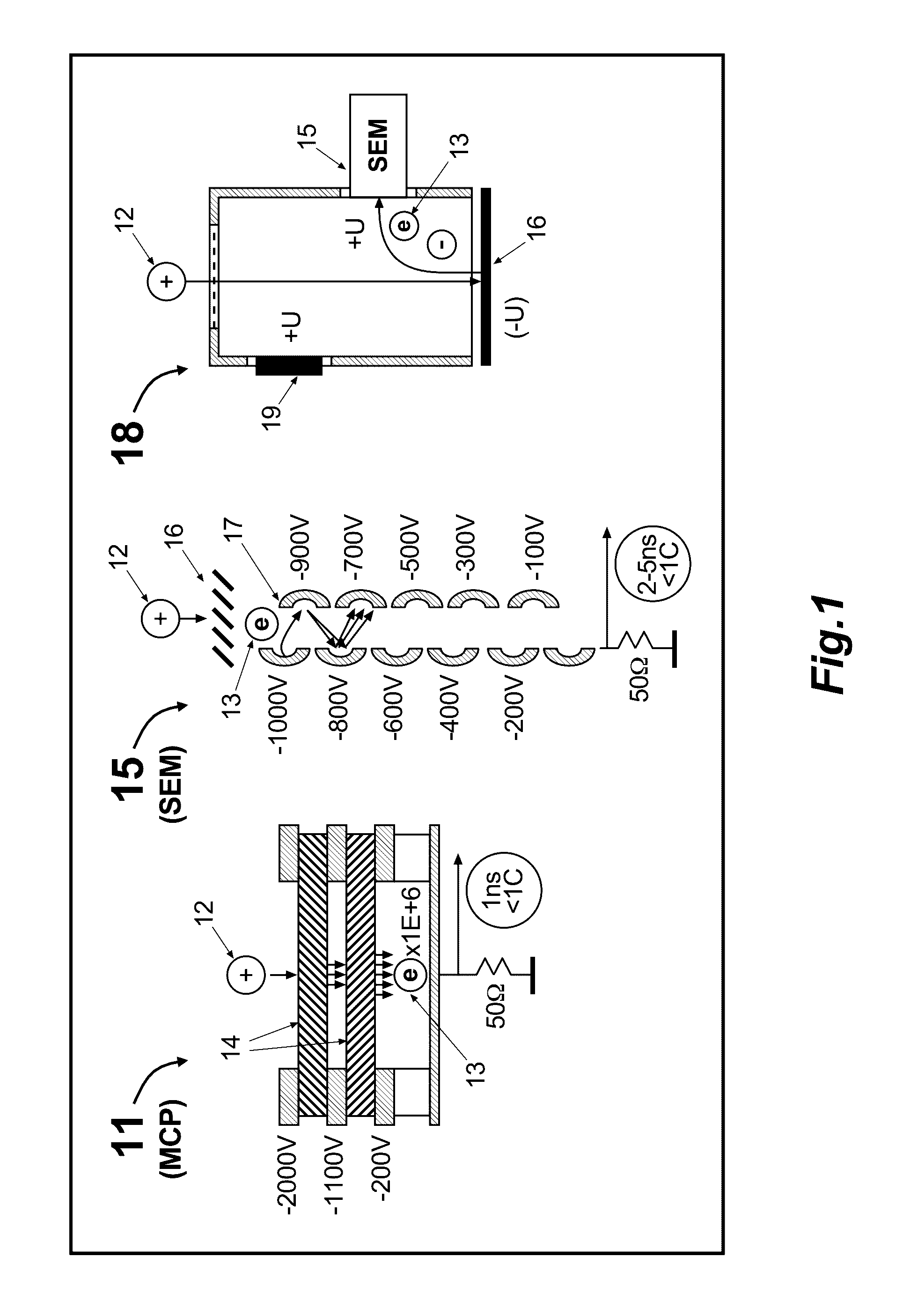
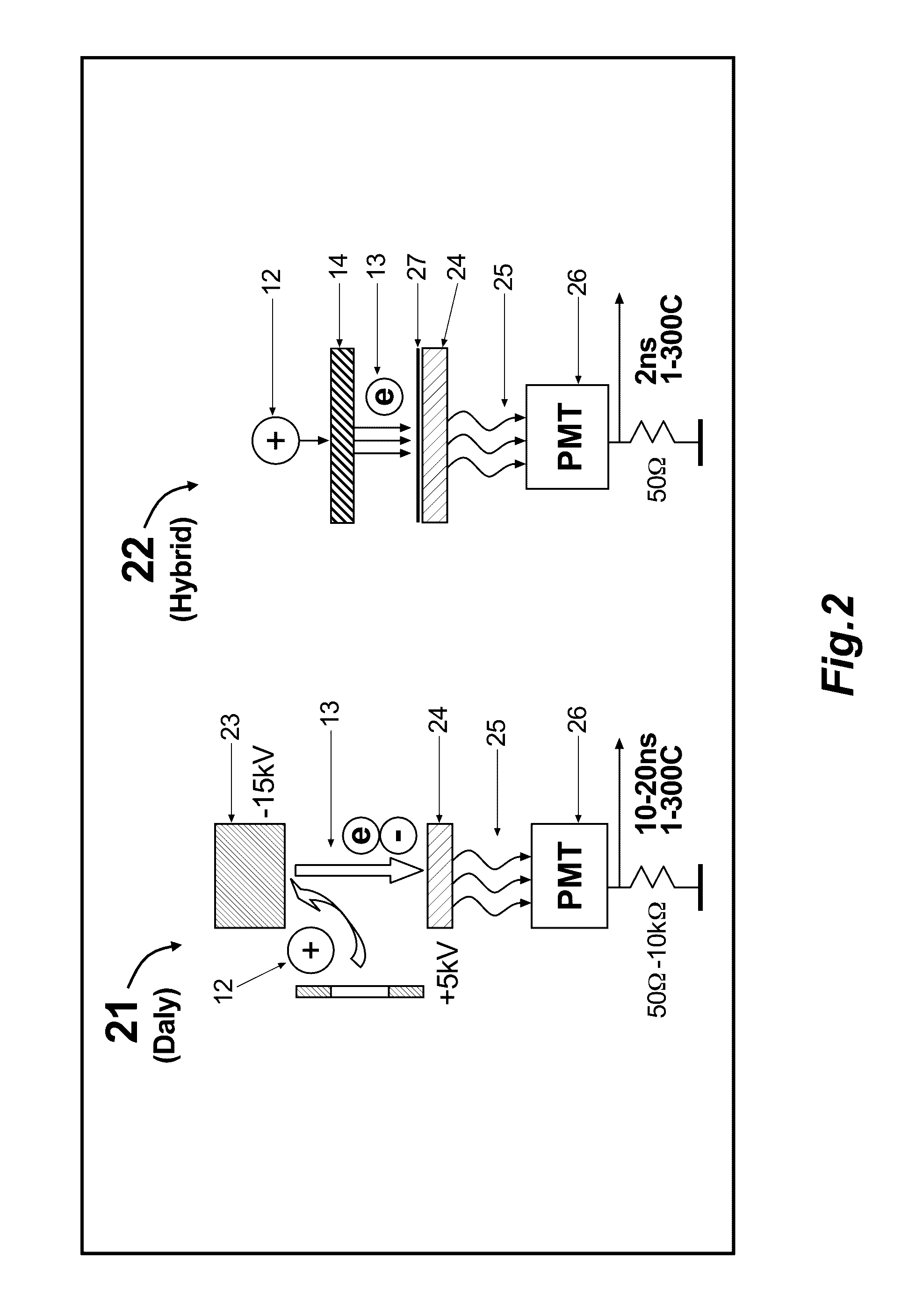
[0059]Referring to FIG. 4, there is presented a zoom view of FIG. 3 showing a feasible detector position 32 within the MR-TOF MS 31 at which the detector 41 may reside. In one embodiment 41 of the present invention, the improved time-of-flight detector 41 includes: a conductive converter 46 facing an ion beam 42 and placed adjacent to a drift space 45 of the MR-TOF MS 31; a mesh-coated side window 48 within the drift space 45; magnets 47 oriented orthogonal to the window 48 position; an organic fast scintillator 24 coated or covered by a conductive mesh 4; and a photomultiplier 26 with an extended life time and fast time response. In a sense, the detector 41 is similar to the wide spread the Daly detector 21 of FIG. 2, except the detector 41 of FIG. 4 includes a...


PUM


Abstract

There is proposed a right angle time-of-flight detector (41, 117, 124, 143, 144, 145) comprising a conductive converter (46) for emitting and accelerating secondary electrons, a magnetic field formed by at least one magnet (47) for deflecting the secondary electrons at a right angle and a sealed photo-multiplier (26). The detector is expected to provide an extended resource and dynamic range and may be fit into tight assemblies, such as MR-TOF MS.

Description

TECHNICAL FIELD[0001]This disclosure generally relates to mass spectroscopic analysis and more specifically relates to improving the dynamic range and life time of detectors for time-of-flight mass spectrometers and multi-reflecting time-of-flight mass spectrometers.BACKGROUND[0002]Detection of individual ions in time-of-flight mass spectrometers (TOF MS) requires nanosecond-level detector speeds and approximately 1E+6 gain. Detector's dynamic range and life time are the primary concerns. Parameters of existing time-of-flight detectors limit the combination of resolution, speed, dynamic range, and robustness. Typical TOF detectors have 1 Coulomb resource, measured by the output current, while modern pulsed ion sources may form ion fluxes up to 1E+9 ion / sec. At 1E+6 gain the detector's output current reaches 0.1 mA and, thus, lifetime is limited to 10000 second (3 hrs) only.[0003]Dual microchannel plate (MCP) detectors are capable of sub-nanosecond-detection speeds at 1E+6 gain. Howe...

Claims


Application Information

Patent Timeline
Patent Type & Authority Applications(United States)
IPC IPC(8): H01J49/40G01T1/20
CPCG01T1/20H01J49/406H01J49/025H01J49/40H01J49/36
Inventor VERENCHIKOV, ANATOLY N.VOROBYEV, ALEKSEY
Owner LECO CORPORATION
Why Eureka
Try Eureka