

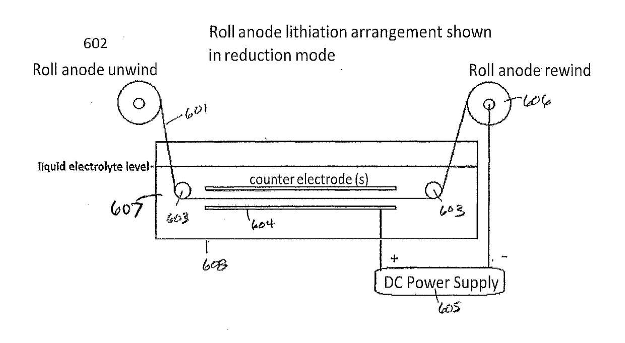
Methods for alkaliating roll anodes
an anode and roll technology, applied in the field of anode materials, can solve the problems of inability to cycle a battery for a long time, so as to achieve safe and practical use, facilitate the cutting of sheets, and increase the electrochemical potential
- Summary
- Abstract
- Description
- Claims
- Application Information
AI Technical Summary
Benefits of technology
Problems solved by technology
Method used
Image

Examples
example 1
Using Forward / Reverse Method Following Rest Period Method
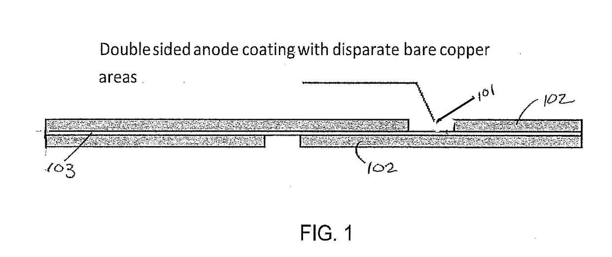
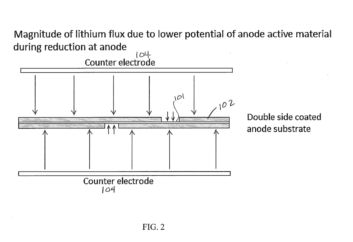
[0057]A 4.6×3.2 cm2 area anode electrode, coated in a pattern with a graphite-silicon blend on both sides of a copper substrate so that a 0.5 cm margin was bare on the one long edge of each side (approximately 10% bare copper), was mounted in a frame and placed between counter electrodes using 2 cm spacing. A GBL solvent and 0.5M LiCl salt solution held at 25° C. enveloped the electrodes. Carbon dioxide was bubbled through the solution. Using a Maccor 4200 battery tester, a forward (reducing) current density of 0.9 mA / cm2 was produced for 150 seconds exhibiting a cell voltage of +6 V (FIG. 6). This pulse was immediately followed by a rest period for 30 seconds producing a cell voltage of 0 V. At the early stages of pre-lithiation, there is a minimum amount of intercalated Li in the anode and therefore current reversal was not yet introduced. Forward / rest pulses were carried out for 4 consecutive cycles before introducing forwa...
example 2
Using Rest Period Method
[0058]A 4.6×3.2 cm2 area anode electrode, coated in a pattern with a graphite-silicon blend on both sides of a copper substrate so that a 0.5 cm margin was bare on the one long edge of each side (approximately 10% bare copper), was mounted in a frame and placed between counter electrodes using 2 cm spacing. A GBL solvent and 0.5M LiCl salt solution held at 25° C. enveloped the electrodes. Carbon dioxide was bubbled through the solution. Forward (reducing) currents and rest periods were produced with the use of the previously mentioned Dynatronix (DuPR10) power supply. The pulses were defined as +6 V for Vmax with a duration of 500 milliseconds (reducing), and rest period of 500 milliseconds at 0 V. These pulses were repeated continuously for 90 minutes. This method produces pre-lithiated anodes with bare Cu areas with no Li0 metal particles. A 2.5 cm2 electrode sample was cut and mounted against separators and lithium foil to form a half cell. After soaking i...
example 3
Varying Forward / Reverse Current Ratios
[0059]A 6 cm wide copper substrate, 5 cm of which are coated on both sides with a graphite-silicon blend, was placed between counter electrodes using two centimeter spacing. A GBL solvent and 0.5M LiCl salt solution held at 25 degrees C. enveloped the electrodes. Carbon dioxide was bubbled through the solution. Total process time was 90 minutes. For the first 25% of the process time, a forward (reducing) current of 1.2 mA / cm2 was produced for 155 seconds. This pulse was immediately followed by a reverse current of 0.15 mA / cm2 for a duration of 25 seconds. For the second 25% of the process time, a forward (reducing) current of 1.0 mA / cm2 was produced for 155 seconds. This pulse was immediately followed by a reverse current of 0.3 mA / cm2 for a duration of 25 seconds. For the third 25% of the process time, a forward (reducing) current of 1.0 mA / cm2 was produced for 155 seconds. This pulse was immediately followed by a reverse current of 0.6 mA / cm2 ...
PUM
| Property | Measurement | Unit |
|---|---|---|
| Fraction | aaaaa | aaaaa |
| Fraction | aaaaa | aaaaa |
| Fraction | aaaaa | aaaaa |
Abstract
Description
Claims
Application Information