Method and Apparatus for Infrared Scattering Scanning Near-field Optical Microscopy with High Speed Point Spectroscopy

a near-field optical microscopy and high-speed point spectroscopy technology, applied in the direction of scanning probe techniques, optical radiation measurement, instruments, etc., can solve the problems of large background scattering ebg, severe practical limits on the amount of background scattering amplification, and each has significant limitations. achieve high-speed demodulation, high sensitivity measurement, rapid and accurate calculation

Active Publication Date: 2017-08-03
BRUKER NANO INC
View PDF0 Cites 11 Cited by
  • Summary
  • Abstract
  • Description
  • Claims
  • Application Information

AI Technical Summary

Benefits of technology

[0033]Therefore, the object of the current invention is to overcome the limitations of the prior art in IR s-SNOM. Specifically, the current invention enables efficient, high sensitivity measurements of the amplitude and phase of the near field tip scattered light. It also enables high speed demodulation of the near field signal in support of high speed nanoscale spectroscopy and chemical imaging. The current invention also enables rapid and accurate calculations of near field phase while eliminating the need for an in situ reference sample. In some embodiments, errors due to interferometer path length and physical separation are reduced. In other embodiments, appropriate samples of interest are mounted on or in close proximity to a reference region with constant or known properties over the wavelength range of interest, while still enabling a rapid and efficient method for producing reflection / absorption spectra over a range of wavelengths. In some embodiments, the spectra comprise IR absorption spectra which can enable chemical analysis and identification.

Problems solved by technology

These unwanted interactions result in large background scattering Ebg.
While each of these approaches has achieved experimental success, each has significant limitations.
Unfortunately, in practice, there have been severe practical limits on amount of this amplification.
The fact that the reference intensity and background intensity are similar can lead to large errors in measurements of optical phase.
There are several disadvantages of the pseudoheterodyne approach, namely (1) loss in signal-to-noise; (2) loss in measurement speed; and (3) increased measurement complexity.
The loss in signal-to-noise ratio comes from the fact that the pseudoheterodyne technique distributes the energy from the Enf signal across many frequency bands, specifically numerous sidebands around the cantilever oscillation frequency and its higher harmonics.
The reference arm mirror and associated actuators are relatively large mechanical devices and thus limited in practice to oscillations in the 100's of Hertz range.
The narrow bandwidth required to demodulate the sideband thus slows down the measurement since it requires longer integration times and thus makes the entire measurement much slower.
Another major limitation of prior art s-SNOM systems is the inability to easily calculate a spectrum that closely resembles a traditional infrared absorption spectrum without complicated post-processing involving an in situ reference.
Unfortunately, at each wavelength, the optical phase has an unknown and varying phase offset.
This in situ reference requirement has dramatically limited the types of samples that can be successfully measured, as many if not most real world samples do not have a suitable reference material available.
Further, any errors in either the measured or assumed phase of the in situ reference sample lead directly to errors in the calculated spectrum of an unknown sample.
In practice, absorption spectra calculated from prior art s-SNOM measurements have contained distortions in absorption band shapes, offsets in absorption peak positions, and errors in relative absorption peak heights.
These errors lead to complications in the interpretation of s-SNOM spectra and discrepancies from the standard spectra known from materials databases.
Additional errors may be present in systems such as FIG. 1A, or in other system with similar arrangements.
The disadvantage of interferometric detection is that it is extremely sensitive to differential changes in the optical path length between the sample arm and reference arm, for example due to temperature or air current fluctuations.
Next we turn to issues of spectroscopic measurements in the prior art using s-SNOM techniques.
This technique requires sophisticated femtosecond lasers which can be expensive, complicated, power limited and have limited spectral coverage.
To obtain spectra from this technique, however, is usually extremely tedious.
As such it has been impractical to use the spatio-spectral technique for rapid point spectroscopy, i.e. measuring the absorption spectrum of a single point.

Method used


Image

  • Method and Apparatus for Infrared Scattering Scanning Near-field Optical Microscopy with High Speed Point Spectroscopy
  • Method and Apparatus for Infrared Scattering Scanning Near-field Optical Microscopy with High Speed Point Spectroscopy
  • Method and Apparatus for Infrared Scattering Scanning Near-field Optical Microscopy with High Speed Point Spectroscopy

Examples


Embodiment Construction

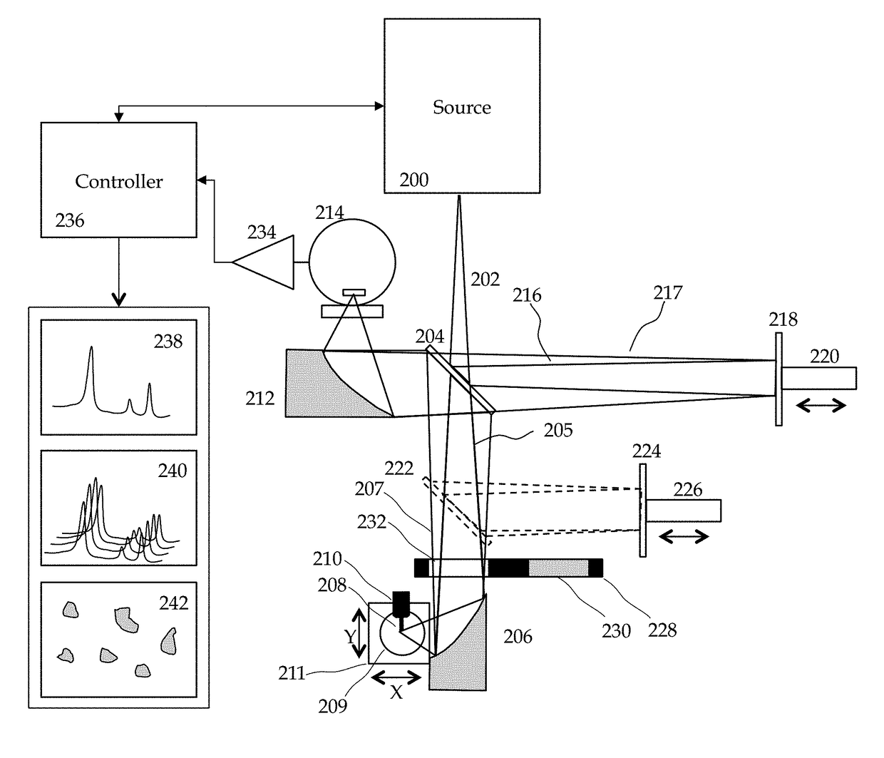
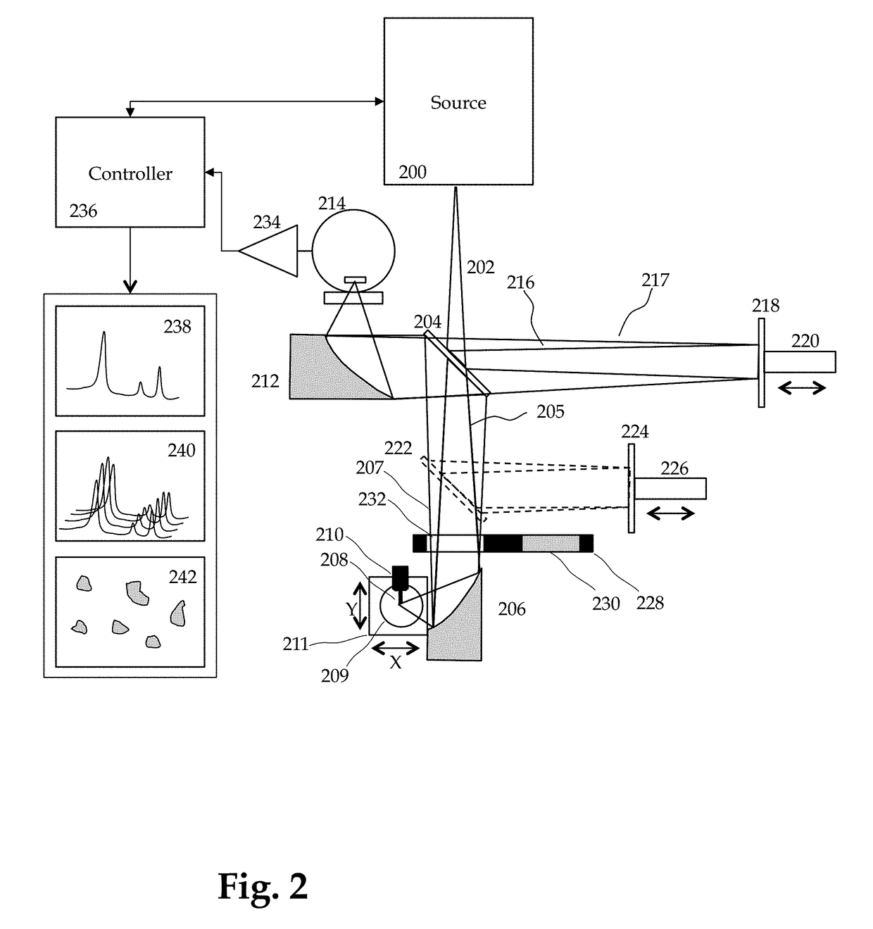
[0054]FIG. 2 shows a simplified schematic of an embodiment of the current invention. Infrared light 202 is emitted from source 200 towards a beam splitter 204. In FIG. 2, the light 202 is shown as diverging, but it may also be substantially collimated. Light 205 that passes through the beam splitter continues towards a focusing optic 206 that focuses the infrared light onto a sample 209 in the vicinity of the end 208 of a probe 210 of a probe microscope. (FIG. 2 shows a top view looking down on a sample and a cantilever probe—the probe tip and tip apex are not illustrated in this view.) Light scattered from the tip and sample is collected by collection optics. In the simplest implementation the collection optics are the same as focusing optics 206, but alternate and / or additional collection optics can be used instead. Light 207 collected from the collection optic is returned to the beam splitter 204 where it is focused via another focusing optic 212 onto the surface of an infrared d...


PUM

PropertyMeasurementUnit
wavenumberaaaaaaaaaa
optical propertyaaaaaaaaaa
probe microscopeaaaaaaaaaa

Abstract

This invention involves measurement of optical properties of materials with sub-micron spatial resolution through infrared scattering scanning near field optical microscopy (s-SNOM). Specifically, the current invention provides substantial improvements over the prior art by achieving high signal to noise, high measurement speed and high accuracy of optical amplitude and phase. Additionally, it some embodiments, it eliminates the need for an in situ reference to calculate wavelength dependent spectra of optical phase, or absorption spectra. These goals are achieved via improved asymmetric interferometry where the near-field scattered light is interfered with a reference beam in an interferometer. The invention achieves dramatic improvements in background rejection by arranging a reference beam that is much more intense than the background scattered radiation. Combined with frequency selective demodulation techniques, the near-field scattered light can be efficiently and accurately discriminated from background scattered light. These goals are achieved via a range of improvements including a large dynamic range detector, careful control of relative beam intensities, and high bandwidth demodulation techniques. In other embodiments, phase and amplitude stability are improved with a novel s-SNOM configuration. In other embodiments an absorption spectrum may be obtained directly by comparing properties from a known and unknown region of a sample as a function of illumination center wavelength.

Description

RELATED APPLICATIONS[0001]This application is a Continuation of U.S. application Ser. No. 14 / 634,859, filed Mar. 1, 2015 which is a Continuation-in-Part of U.S. application Ser. No. 14 / 322,768, filed Jul. 2, 2014 which is in turn a Continuation-in-Part of U.S. application Ser. No. 13 / 835,312, filed Mar. 15, 2013BACKGROUND OF THE INVENTION[0002]Scattering scanning near field optical microscopy (s-SNOM) operates by interacting a sharp probe tip of a probe microscope with a sample surface and collecting light scattered from the region of tip-sample interaction. Using this technique it is possible to measure the optical properties of samples with a spatial resolution far below the conventional diffraction limits. The resolution improvement comes from a local enhancement of the incident radiation field due to the sharp tip. The enhanced radiation field interacts with the sample and then scatters radiation into the far field. This near-field enhancement increases the amount of radiation s...

Claims


Application Information

Patent Timeline
Patent Type & Authority Applications(United States)
IPC IPC(8): G01Q60/18G01N21/35G01N21/47
CPCG01Q60/18G01N21/47G01N2201/0612G01N2201/10G01N21/35G01Q30/02G01Q60/22G01N21/39G01N21/4738
Inventor YANG, HONGHUAKJOLLER, KEVINBERWEGER, SAMPRATER, CRAIG
Owner BRUKER NANO INC
Why Eureka
Try Eureka