Implantable Electrode

a technology of implantable electrodes and electrodes, which is applied in the field of implantable materials and devices, can solve the problems of conductive polymers that remain sensitive to changes in impedance, the bio-fouling of implanted devices or materials refers to the uncontrolled growth of tissue on the device or material, and the inability to withstand changes in impedance, so as to achieve no toxic effect, inhibit cell adhesion, and inhibit cell growth

Inactive Publication Date: 2017-08-31
LUXEMBOURG INST OF SCI & TECH LIST
View PDF3 Cites 4 Cited by
  • Summary
  • Abstract
  • Description
  • Claims
  • Application Information

AI Technical Summary

Benefits of technology

[0024]Inhibition of cell adhesion and cell growth on InN means that these phenomena are prevented or significantly slowed down, depending on the cells that are contacted by InN. As cell growth is inhibited on InN, the phenomenon of bio-fouling described above is reduced as compared to known implantable electrode materials. The effect of reduced bio-fouling or bio-adhesion is an observed improvement of the signal to noise ratio that is measurable for electrical signals that are carried by the electrode. Indeed, once an appropriate contact has been established between the electrode and the cell / tissue during implantation, the quality of the contact is not impaired by bio-fouling. The longevity of the implant is therefore enhanced, which reduces the need for maintenance of the electrode and / or repeated surgery for the implanted person.
[0025]While polymer coatings have been suggested to improve on the biocompatibility of known implantable conductive electrodes, the use of InN electrode eliminates the need for a specific coating, as the electrode material itself exhibits biocompatibility with the cells / tissue that are directly contacted by the electrode. An implantable electrode in accordance with the present invention is therefore easier to produce and to maintain as known implantable electrodes made of other materials.
[0026]As the use of an InN electrode eliminates the need for a polymer coating, issues relating to the toxicity of polymers are alleviated. Toxicity levels of InN have been found to be very low.

Problems solved by technology

Biocompatible electrodes for cell stimulation or cell monitoring are still needed as a building block for devices acting as brain mechanical interfaces.
Further, bio-fouling of an implanted device or material refers to the uncontrolled growth of tissue on the device or material.
However, conductive polymers remain very sensitive to changes in impedance caused by bio-fouling or the uptake of the materials in resident immune cells of the brain [3].

Method used


Image

  • Implantable Electrode
  • Implantable Electrode
  • Implantable Electrode

Examples


Embodiment Construction

[0038]This section describes the invention in further detail based on preferred embodiments and on the figures. It should be understood that technical features presented for a specific embodiment may be combined with features of other embodiments, unless specifically noted otherwise. First, the materials and methods used for obtaining the presented results are described.

Materials and Methods

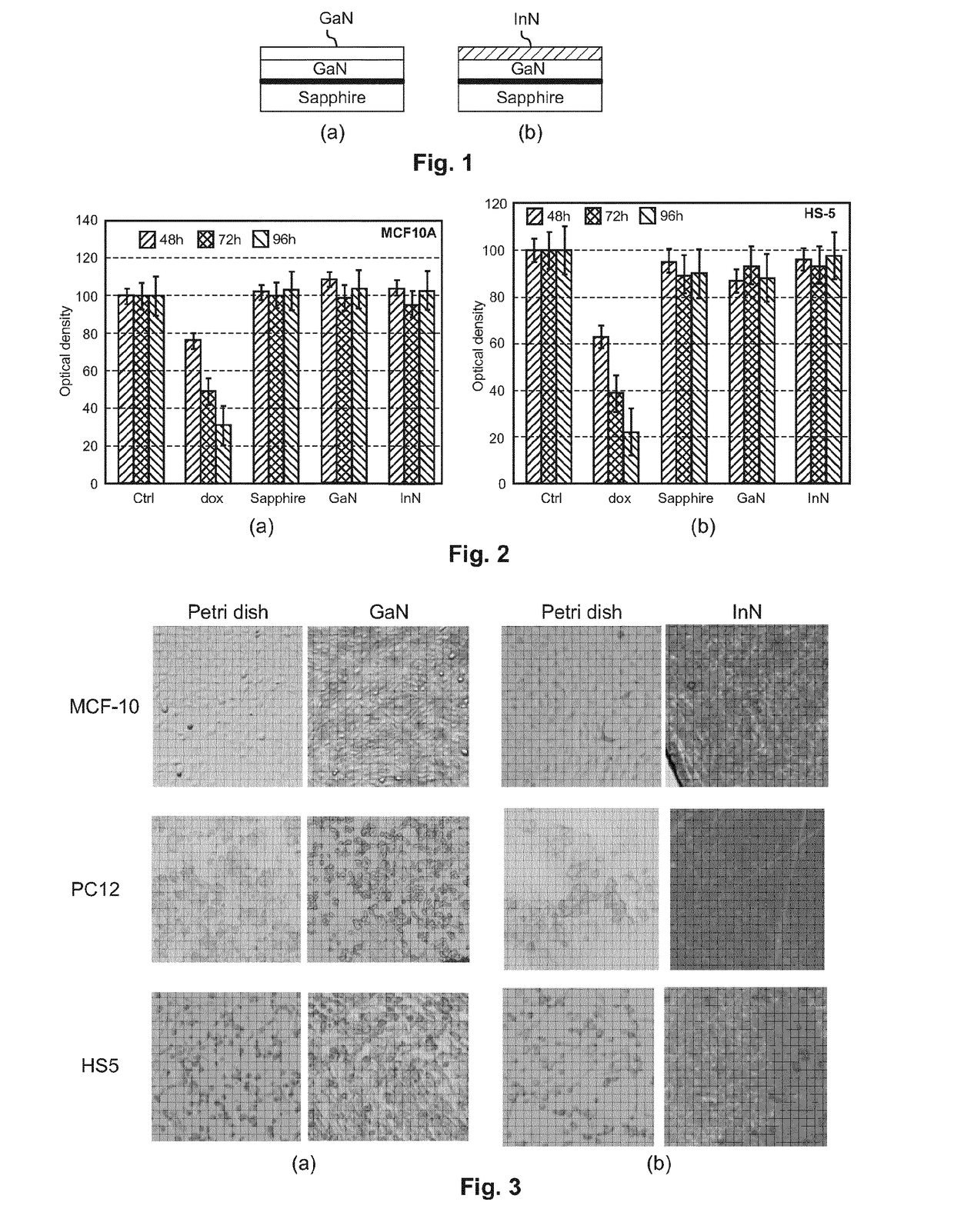
[0039]To simulate cell behavior in the presence of a device comprising a top layer, i.e. a cell-contacting layer, comprising Indium nitride InN material, different structures were synthesized by using Chemical Vapor Deposition, CVD, on Sapphire or silicon substrate. The structures shown in FIGS. 1a and 1b comprise a bottom insulating layer of Sapphire, which acts as a substrate for several layers which form an electrode. The top layer is the only layer which is directly contacted with biological cells during tests. FIG. 1a shows a cell-contacting top layer made of GaN, while FIG. 1b shows a cell-...


PUM

PropertyMeasurementUnit
thicknessaaaaaaaaaa
humidityaaaaaaaaaa
humidityaaaaaaaaaa

Abstract

According to the present invention, an implantable device comprising an electrode for carrying an electric signal to or from a biological cell or tissue provided. The electrode material is chosen to exhibit desirable properties in terms of electrical conductivity, biocompatibility and bio-fouling. The invention further provides implantable devices comprising such implantable electrodes.

Description

TECHNICAL FIELD[0001]The present invention relates to the field of implantable materials and devices. In particular it relates to an electrode for carrying electrical signals to and / or from biological cells or tissues which are directly contacted by the electrode.BACKGROUND OF THE INVENTION[0002]Several materials and devices have been investigated and proposed to mimic, probe or / and restore activities of different biological tissues and cells. Biocompatible electrodes for cell stimulation or cell monitoring are still needed as a building block for devices acting as brain mechanical interfaces. As an example, the first successful neuroprosthetics-cochlear implant put to practice in the early 1990s is a neural interface device that uses an electrode array to stimulate the auditory nerve in the cochlea with electric impulses. Electrical stimulation of peripheral nerves has gained a lot of interest from clinicians for the treatment of pain, for restoration of motricity functions and for...

Claims


Application Information

Patent Timeline
Patent Type & Authority Applications(United States)
IPC IPC(8): A61N1/05A61L27/30
CPCA61L27/306A61N1/05A61L2430/32A61N1/37A61N1/0526A61N1/0534A61N1/3605A61N1/36125A61N1/36128A61L2400/02A61B5/24
Inventor LENOBLE, DAMIENTHOMANN, JEAN-SEBASTIENPALISSOT, VALERIE
Owner LUXEMBOURG INST OF SCI & TECH LIST
Why Eureka
Try Eureka