Ceramic emitter

a ceramic emitter and emitter technology, applied in ceramicware, pv power plants, other domestic objects, etc., can solve the problems of metal emitter, inability to increase efficiency, degraded by oxidization or recrystallization, etc., and achieve excellent wavelength selectivity and high radiation intensity.

Active Publication Date: 2017-09-07
NEC CORP
View PDF0 Cites 9 Cited by
  • Summary
  • Abstract
  • Description
  • Claims
  • Application Information

AI Technical Summary

Benefits of technology

[0017]The ceramic emitter of the present invention can achieve thermal radiation that exhibits high radiation intensity and excellent wavelength selectivity.

Problems solved by technology

However, a metal emitter has a drawback that it is degraded by oxidization or recrystallization upon being used at a high temperature.
However, when the optical filter 7 is used, it is not possible to increase efficiency unless the emitter reflects / absorbs infrared light other than the wavelength adaptable to the photoelectric conversion cell.
Thus, the configuration has drawbacks that the device structure becomes complicated and realizing a high heat-resistant filter is difficult.
NPL 1 reports an emitter that is configured by forming, on SiC ceramic, a composite coating of alumina or zirconia fibers and erbium aluminum garnet, Er3Al5O12 (ErAG), that has 50% or more porosity and 50 to 500 μm in thickness. FIG. 12 illustrates a thermal radiation spectrum of the ErAG composite and SiC ceramic at 1050° C. Although a selected wavelength radiation can be observed around a wavelength of 1600 nm, there is a drawback that the radiation intensity is relatively smaller compared with SiC that has emissivity of 0.9.
There is a drawback that the emissivity of around 0.7 even at a peak value is relatively smaller compared with SiC whose emissivity is 0.9 thorough the entire wavelength range.
Further, when the wavelength selectivity of emissivity is defined by the ratio of the emissivity at a peak wavelength to the emissivity at a wavelength of 1750 nm, the ratio is 1.7 for a composite of YbAG and alumina, 1.5 for a composite of ErAG and alumina, which are not very good results.

Method used


Image

  • Ceramic emitter
  • Ceramic emitter
  • Ceramic emitter

Examples


example 1

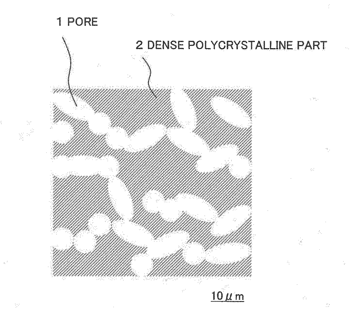
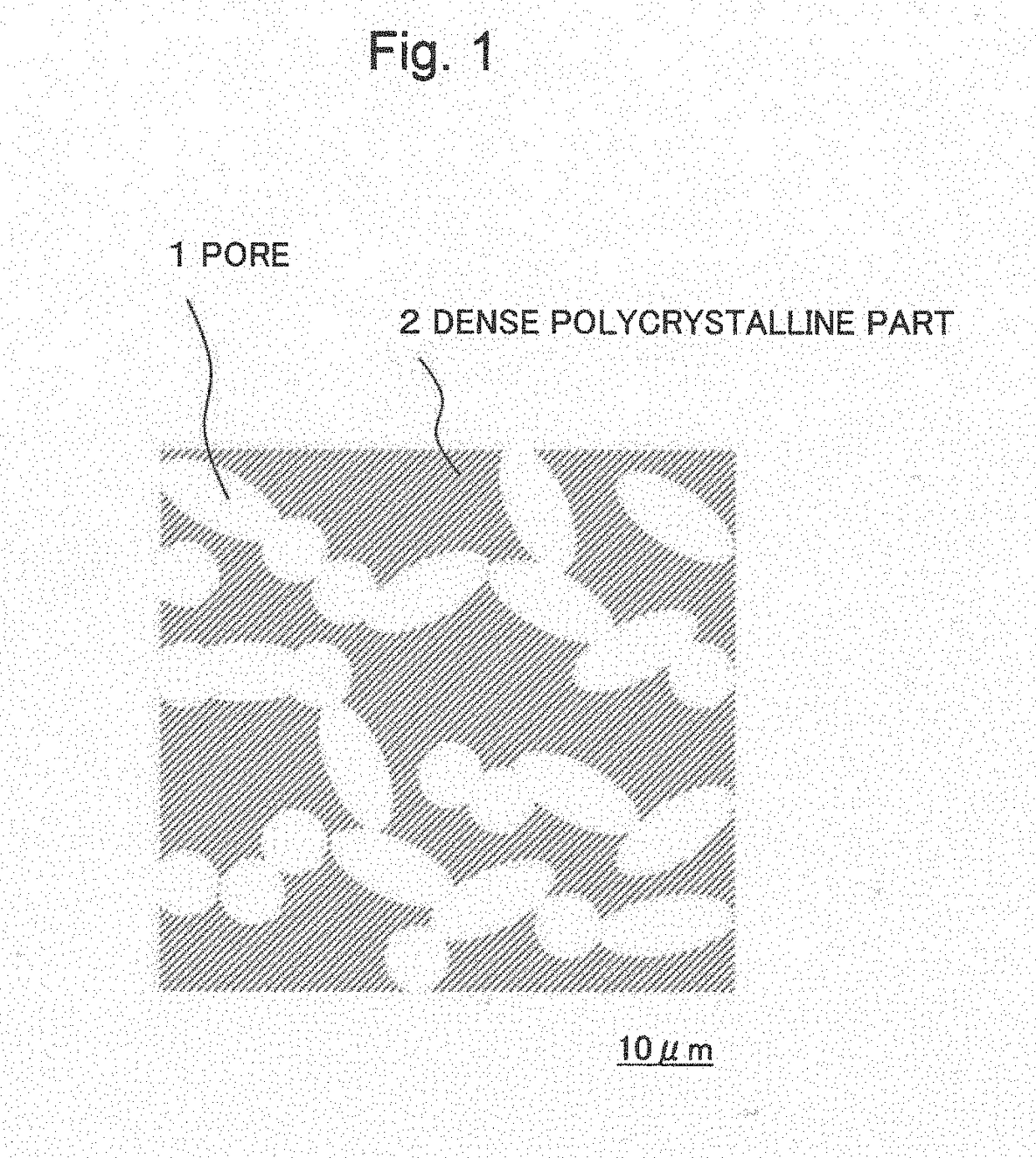
[0040]As materials of a ceramic emitter, Yb2O3 and Al2O3 powders are used and weighed at a stoichiometric mixture ratio such that the mixture becomes Yb3Al5O12 after synthesizing. Subsequently, the mixture is added with ethanol and wet-mixed in an agate mortar, then calcined for two hours at 1600° C. in the atmosphere, thereby obtaining a garnet crystal of the above-described compositional formula by solid-state reaction. Thereafter, the garnet crystal is grounded in an agate mortar, pressed into a pellet, and fired at 1600° C. for 12 hours, thereby obtaining a polycrystalline sintered body of a disc shape. The pellet size after sintering is 12.8 mm in diameter and 1.1 mm in thickness. The porosity of this sintered body is confirmed as 36% by a density measurement using the Archimedes method. Further, to prevent water from infiltrating the pores, the density measurement is performed after coating the surface of the sintered body with a cellulose resin.

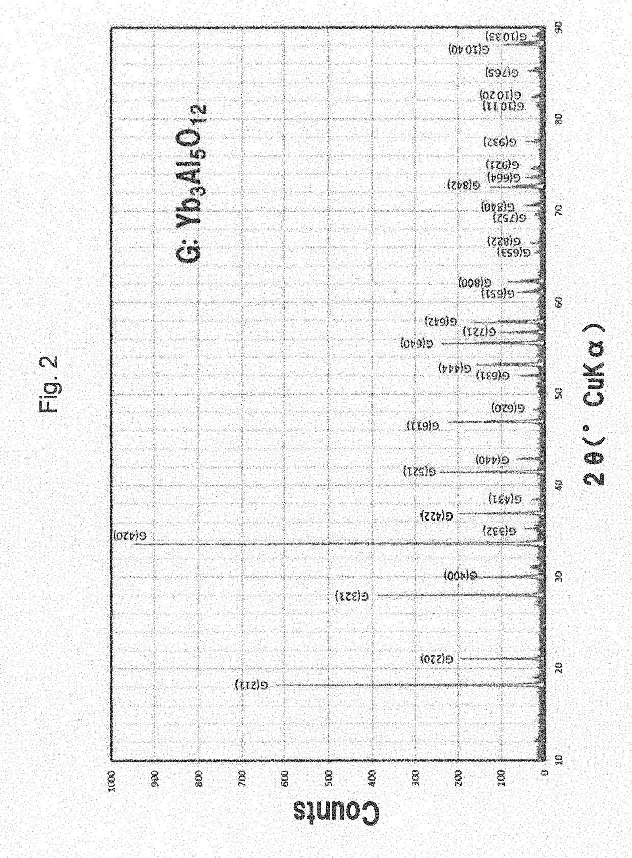
[0041]FIG. 2 illustrates a powd...

example 2

[0043]As materials of a ceramic emitter, Yb2O3 and Ga2O3 powders are used and mixed in the same way as Example 1, calcined at 1600° C. for 2 hours in the atmosphere, pressed into a pellet, and then fired at 1500° C. for 2 hours to obtain a Yb3Ga5O12 sintered body.

[0044]It is confirmed by powder X-ray diffraction that the sintered body obtained in the same way as Example 1 has a single phase garnet structure. Further, the size of the sintered body is 12.7 mm in diameter and 0.9 mm in thickness. The porosity is 32% by the density measurement.

[0045]The thermal radiation spectra of the sintered body are measured at 957° C. and 1017° C. in the same way as Example 1 and the results are illustrated in FIG. 7. In the same way as Example 1, selective radiation can be confirmed at a wavelength of approximately 1000 nm that matches with the sensitivity wavelength of the Si photovoltaic cell, while radiation of a wavelength of 1200 nm or more is suppressed. It is observed that the wavelength se...

example 3

[0046]As materials of a ceramic emitter, Er2O3 and Ga2O3 powders are used and mixed in the same way as Example 1, calcined at 1600° C. for 2 hours in the atmosphere, pressed into a pellet, and fired at 1500° C. for 2 hours to obtain an Er3Ga5O12 sintered body.

[0047]It is confirmed by powder X-ray diffraction that the sintered body obtained in the same way as Example 1 has a single phase garnet structure. Further, the size of the sintered body is 12.7 mm in diameter and 1.0 mm in thickness. The porosity is 25% by the density measurement.

[0048]The result of measuring a thermal radiation spectrum of the sintered body at 1058° C. in the same way as Example 1 is illustrated in FIG. 8, together with the measurement result of SiC at the same temperature. Selective radiation can be confirmed at a wavelength of approximately 1500 nm that matches with the sensitivity wavelength of a GaSb photovoltaic cell, whose band gap corresponds to the wavelength of 1700 nm. The ratio of the emissivity at...


PUM

PropertyMeasurementUnit
porosityaaaaaaaaaa
porosityaaaaaaaaaa
cross-section areaaaaaaaaaaa

Abstract

[Objective] To provide a ceramic emitter that exhibits high radiation intensity and excellent wavelength selectivity.[Solution] A ceramic emitter includes a polycrystalline body that has a garnet structure represented by a compositional formula R3Al5O12 (R: rare-earth element) or R3Ga5O12 (R: rare-earth element) and has pores with a porosity of 20-40%. The pores have a portion where the pores are connected to one another but not linearly continuous, inside the polycrystalline body.

Description

TECHNICAL FIELD[0001]The present invention relates to a ceramic emitter, particularly to a ceramic emitter for a thermophotovoltaic device.BACKGROUND ART[0002]Thermophotovoltaic power generation is a technique of converting thermal radiation to electric power using a photoelectric conversion cell. The thermophotovoltaic power generation is attracting attention as a power generating technology that promises highly efficient power generation by controlling a radiation spectrum, allows to use a variety of thermal sources, and provides high energy density per unit weight.[0003]FIG. 9 illustrates a basic configuration of thermophotovoltaic power generation. The configuration includes: converting heat generated from combustion equipment or heat generated by condensing solar light to infrared radiation by an emitter 4; allowing the infrared light to enter a photoelectric conversion cell 5; and converting the infrared light to electric power. While a variety of emitter materials are reporte...

Claims


Application Information

Patent Timeline
Patent Type & Authority Applications(United States)
IPC IPC(8): C09K11/77H02S10/30H01L31/055C01F17/00C01G15/00
CPCC09K11/7706C01F17/0025C01G15/006C09K11/7701C01P2004/61H02S10/30C01P2006/60C01P2002/30C01P2006/12H01L31/055C04B35/44Y02E10/52C01G15/00C04B35/01C04B38/0074C09K11/7769C04B2235/3224C04B2235/3286C04B2235/6567C04B2235/764C04B2235/77C01F17/34
Inventor SHIBUYA, AKINOBU
Owner NEC CORP
Why Eureka
Try Eureka