
Laser interference lithography system with flat-top intensity profile

a lithography system and intensity profile technology, applied in the field of laser interference lithography system, can solve the problems of insufficient uniformity of grating structure on sample, insufficient uniformity of grating structure, and inability to apply to generate uniform periodic structure over a large sample, etc., to achieve uniform exposure dose, uniform light field, and large sample area

Active Publication Date: 2017-11-16
NAT SUN YAT SEN UNIV
View PDF10 Cites 6 Cited by
  • Summary
  • Abstract
  • Description
  • Claims
  • Application Information

AI Technical Summary

Benefits of technology

The present invention provides a laser interference lithography system that can create a more uniform light field by flattening the intensity profile of laser beams. This allows for a larger sample area to be exposed to the same amount of light, resulting in a more uniform exposure dose.

Problems solved by technology

The LIL system equipped with a Lloyd's mirror is simple in system setup and not susceptible to environmental disturbance, but it can not be applied to generate uniform periodic structures over a large sample area because the energy distribution of the two beams in the system are non-uniform and respectively right and left sides of Gaussian intensity profile.
While the two beams interfere mutually, the exposure dose on the sample region close to the reflecting mirror is higher than that far away from the reflecting mirror, so the uniformity of the grating structure on the sample is not sufficient.
However, the uniformity of the grating structure is still insufficient and the issue arise from Gaussian intensity profile still exists.

Method used


Image

  • Laser interference lithography system with flat-top intensity profile
  • Laser interference lithography system with flat-top intensity profile
  • Laser interference lithography system with flat-top intensity profile

Examples


Embodiment Construction

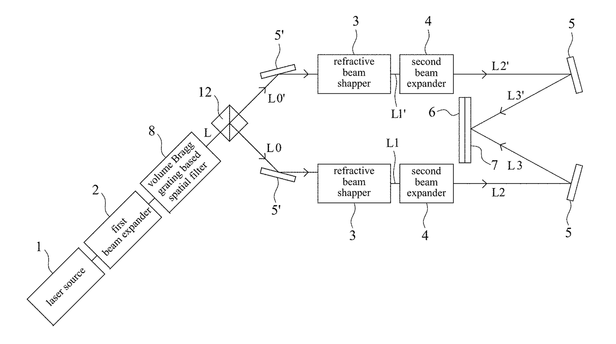
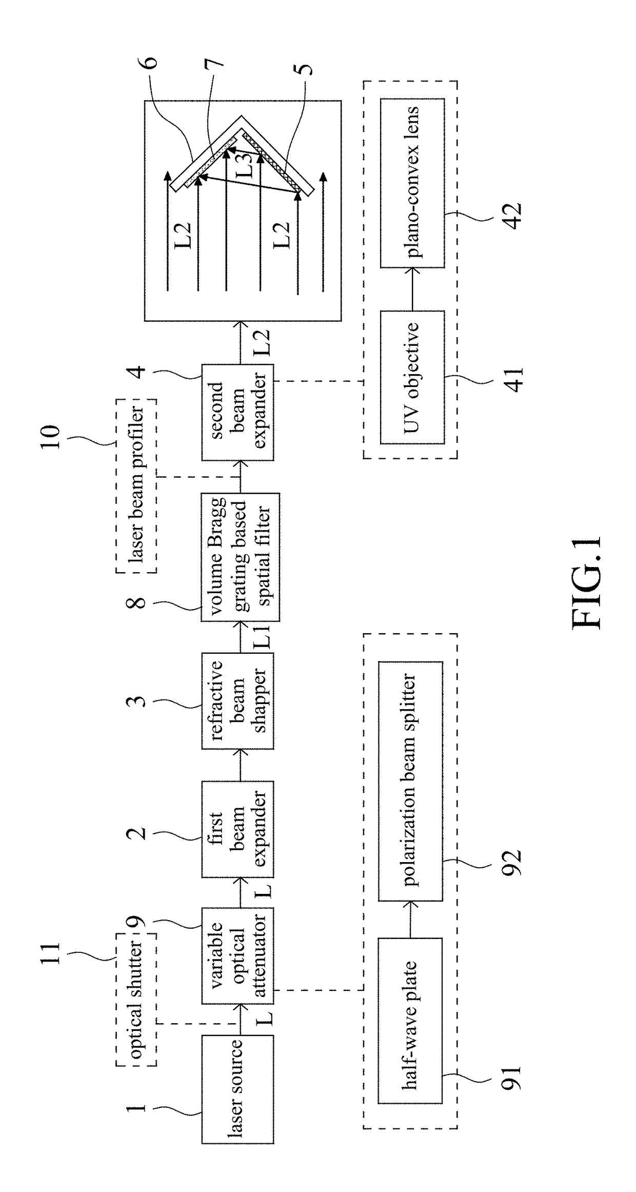
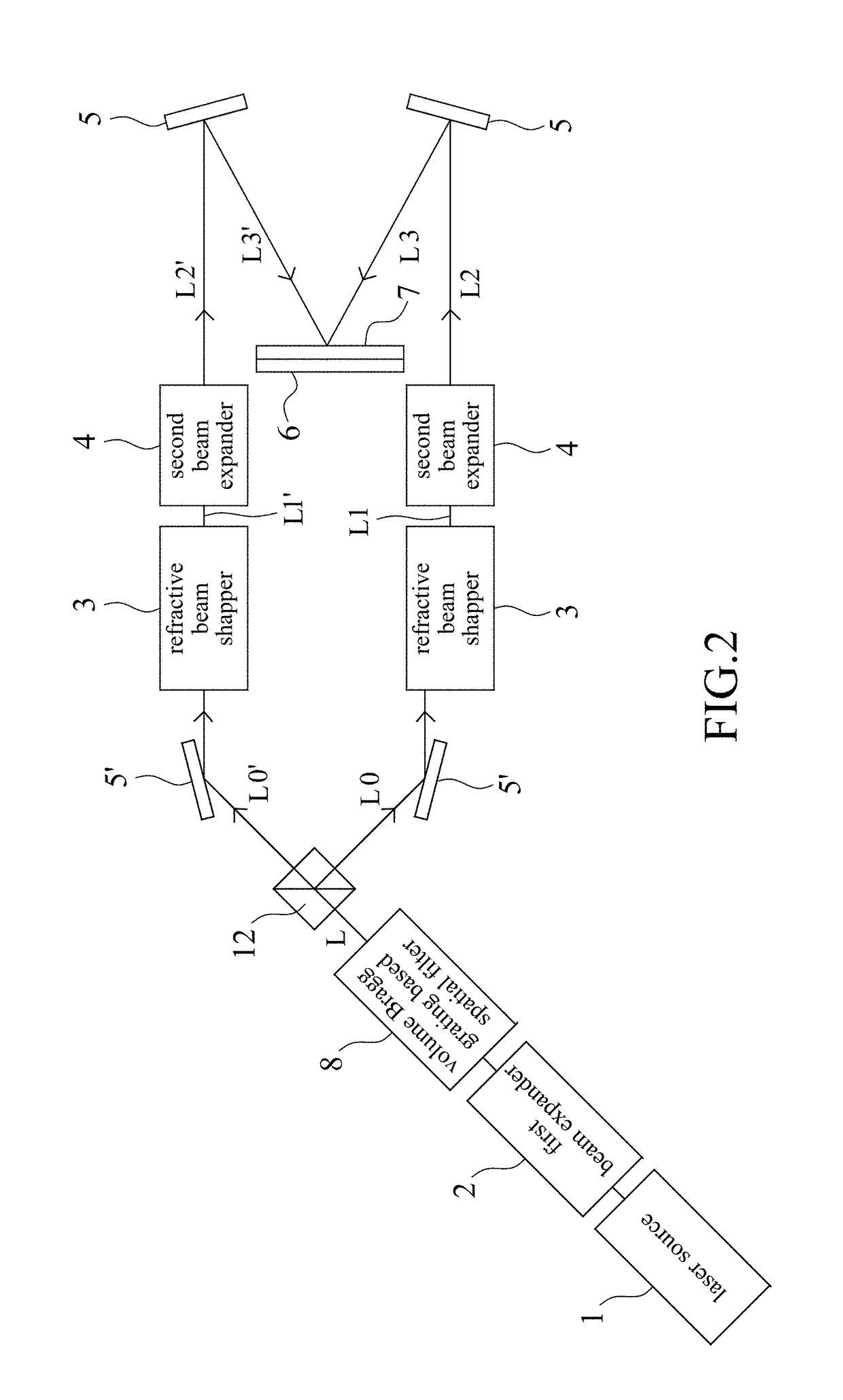
[0013]With reference to FIG. 1, a laser interference lithography system with flat-top intensity profile 100 of a first embodiment of the present invention comprises a laser source 1, a first beam expander 2, a refractive beam shaper 3, a second beam expander 4, a reflector 5 and a sample holder 6. The laser source 1 is provided for emitting a coherent laser beam L whose wavelength is 325 nm, 355 nm, 365 nm, 405 nm, or other ultraviolet (UV) wavelengths. In the first embodiment, a diode-pumped solid-state (DPSS) laser with an output power of 100 mW, a wavelength of 355 nm and a coherent length exceeding 40 m is preferably adapted as the laser source 1, wherein the DPSS laser has a relatively compact size (125 mm×70 mm×45 mm). UV gas lasers such as Helium-Cadmium (He—Cd) laser also can be adapted to emit the coherent laser beam L, but its coherent length is only 30 cm, and with bulky size and shorter lifetime. Preferably, an optical shutter 11 disposed between the laser source 1 and t...


PUM


Abstract

A laser interference lithography system with flat-top intensity profile comprises a laser source for emitting a coherent laser beam, a first beam expander for adjusting the coherent laser beam size, a refractive beam shaper for converting a Gaussian intensity profile inherent to the coherent laser beam into a flat-top one and outputting a first collimated laser beam, a second beam expander for receiving the first collimated laser beam and outputting a second collimated laser beam, a sample holder for holding a substrate, and at least one reflector for reflecting the second collimated laser beam to generate a third collimated laser beam. The second and third collimated laser beams are transmitted to the substrate at a predetermined angle to create an interference pattern exposed onto the substrate.

Description

FIELD OF THE INVENTION[0001]This invention relates to a laser interference lithography system, and more particularly relates to a laser interference lithography system capable of providing a flat-top intensity profile with a large exposure area for nano-patterning.BACKGROUND OF THE INVENTION[0002]Laser interference lithography (LIL) is an inexpensive approach for fabricating periodic structures, wherein LIL utilizes two mutually-interfered coherent laser beams to form periodic interference fringes. While the photosensitive material (e.g. photoresist) is exposed to the interference fringes, the patterns of the periodic interference fringes can be transferred to the photoresist to form periodic grating structures, and furthermore, the periodic grating structures on the photoresist can be transferred to various materials by etching techniques. Low-cost and high-throughput LIL is widely used for distributed feedback semiconductor laser fabrication for telecommunication applications, whi...

Claims


Application Information

Patent Timeline
IPC IPC(8): G02B27/09G02B27/28
CPCG02B27/0927G02B27/095G02B27/283G02B27/0944G03F7/70408
Inventor HUNG, YUNG-JRCHANG, HAN-JUNG
Owner NAT SUN YAT SEN UNIV
Learn More