Method of fabricating tungsten scandate nano-composite powder for cathodes

a technology of tungsten scandate and composite powder, which is applied in the direction of discharge tube/lamp details, basic electric elements, chemistry apparatus and processes, etc., can solve the problem that commercially available cathodes do not produce an adequate amount of current density, and achieve uniform distribution of emissive materials, improve emission uniformity, and reduce the work function of the emission surface

Active Publication Date: 2017-12-14
RGT UNIV OF CALIFORNIA
View PDF1 Cites 5 Cited by
  • Summary
  • Abstract
  • Description
  • Claims
  • Application Information

AI Technical Summary

Benefits of technology

[0023]The powders prepared by the sol-gel methods have a narrow distribution of particle sizes and a very uniform dispersion of nanosized Scandia particles joined to the tungsten grains. The powder particle sizes can range from nanometers to micrometers and can be controlled by adjusting the sol-gel processing parameters. The scandia concentration in the processed powders can also be controlled. Consequently, the parameters of the densified cathode matrix structures that can be fabricated from the powders can be controlled to have high porosity, uniform grain size and scandia distribution, and open pore distribution.
[0025]After the powder is produced, sintered into a pellet, and impregnated with emissive materials, the structure can be machined to provide a cathode with desired shapes to fit into many different devices such as an electron gun. The uniform cathode matrix structure makes the emission surface acquire a more uniform distribution of emissive material (e.g. barium, oxygen, and scandium), thereby improving the emission uniformity and lowering the work function of the emission surface and the cathode is more resistive to ion bombardment.
[0026]The resulting cathodes can be produced in desired shapes to fit into specific electron gun configurations and other applications. These cathodes have high current emission and can be machined with high tolerance and required surface finish for the intended engineering applications.
[0029]Another aspect of the technology is to provide an efficient process for producing high current density and long-life cathodes for high-power terahertz vacuum electron devices.
[0030]It is also an aspect of the technology to provide a method of fabrication that allows control over the material particle size, particle composition and pore size and distribution by manipulation of the process parameters.
[0031]A further aspect of the technology is to provide a cathode material that is comparatively inexpensive to produce and simple to use with existing industrial scale systems.

Problems solved by technology

Commercially available cathodes do not produce an adequate amount of current density to build sensible high power devices.
For example, typical commercially available cathodes produce 2 to 8 A / cm2 of current density, with the lifespan being limited to just 1,000 hours at the higher end of emission density.

Method used


Image

  • Method of fabricating tungsten scandate nano-composite powder for cathodes
  • Method of fabricating tungsten scandate nano-composite powder for cathodes
  • Method of fabricating tungsten scandate nano-composite powder for cathodes

Examples


example 1

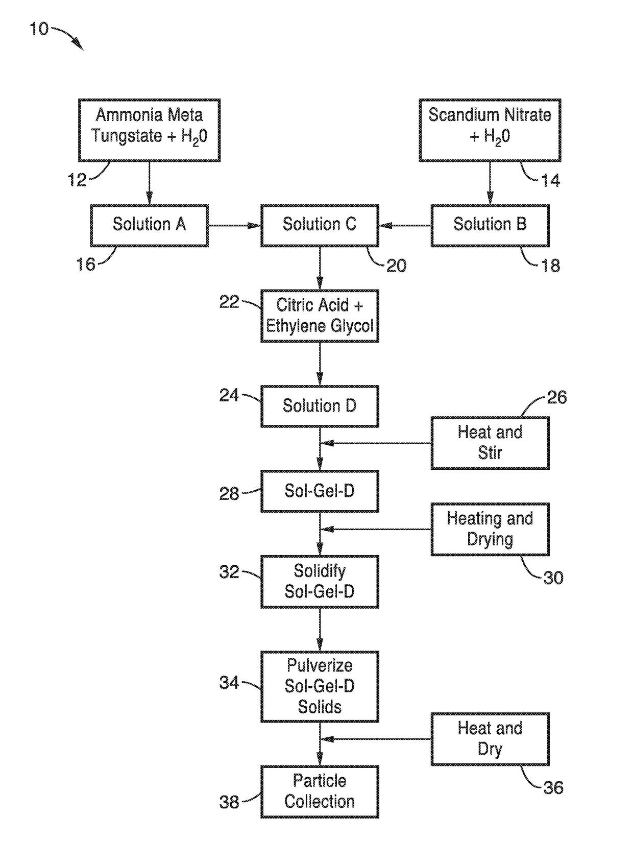
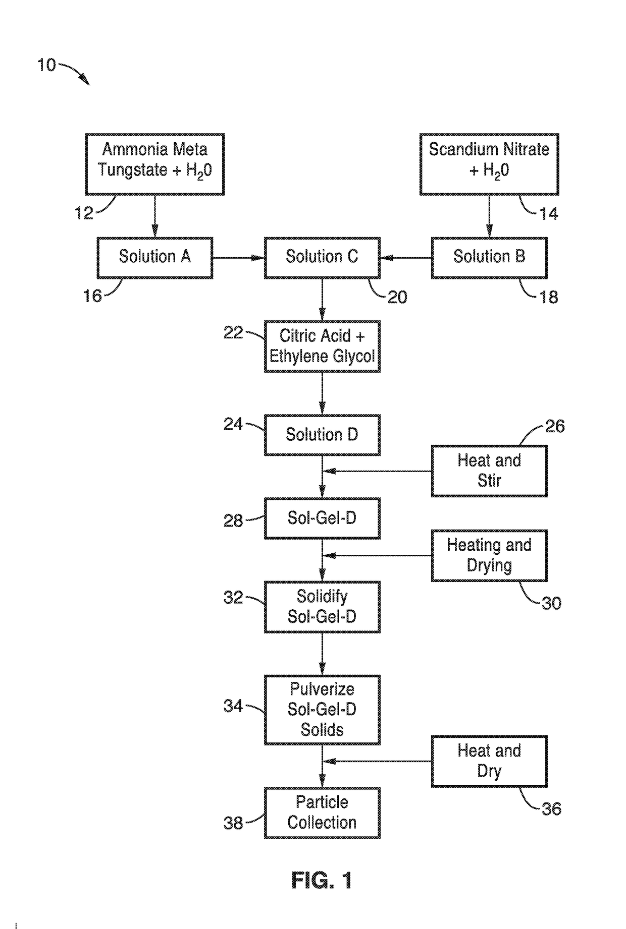
[0067]In order to demonstrate the fabrication methods, a nanocomposite 5% scandate tungsten powder was produced, formed into a cathode structure and tested. In this example, about 25.468 grams of ammonium meta tungstate [(NH4)6H2W12O40] was mixed with between 100 ml to about 300 ml of deionized water and the solution was stirred to with to dissolve the salt to produce a first solution. Then, about 3.366 grams of scandium (III) nitrate [Sc(NO3)3] was mixed with about 20 ml to about 200 ml of deionized water with scandium nitrate; stir the solution to dissolve the salt and produce a second solution. The weight of the scandium (III) nitrate can be adjusted accordingly to achieve a lower or higher percentage of scandia in the final powder. The preferred percentage of scandia is between about 2% and about 8% by weight.

[0068]The first and second solutions were combined in a flask and about 10 grams to about 30 grams of citric acid [C6H8O7] and ethylene glycol, [99%, C2H6O2], were added an...

example 2

[0074]To further demonstrate the technology, several quantities of ammonium metatungstate / (NH4)6H2W12O40 and scandium(III) nitrate / Sc(NO3)3 were weighed and mixed with deionized water and stirred to produce solutions. Specifically, 200 mL of deionized water was added to the ammonium meta tungstate in a 300 mL beaker and placed on a stirring plate and spun at 350 RPM's to dissolve the chemicals. Similarly, the scandium nitrate was placed in 100 mL of deionized water and then put on a stirring plate and spun at 350 RPM's to dissolve chemicals.

[0075]Equal parts ethylene glycol and citric acid / C6H8O7 were mixed in a 50 mL beaker, first ethylene glycol and then the citric acid was added. The scandium and tungstate solutions were combined and placed into a 500 mL Erlenmeyer flask and then 20 grams of citric acid and ethylene glycol were immediately added to the Erlenmeyer flask.

[0076]A heated oil bath was prepared by filling a Pyrex beaker (No. 3140) with silicone oil halfway up the beake...

example 3

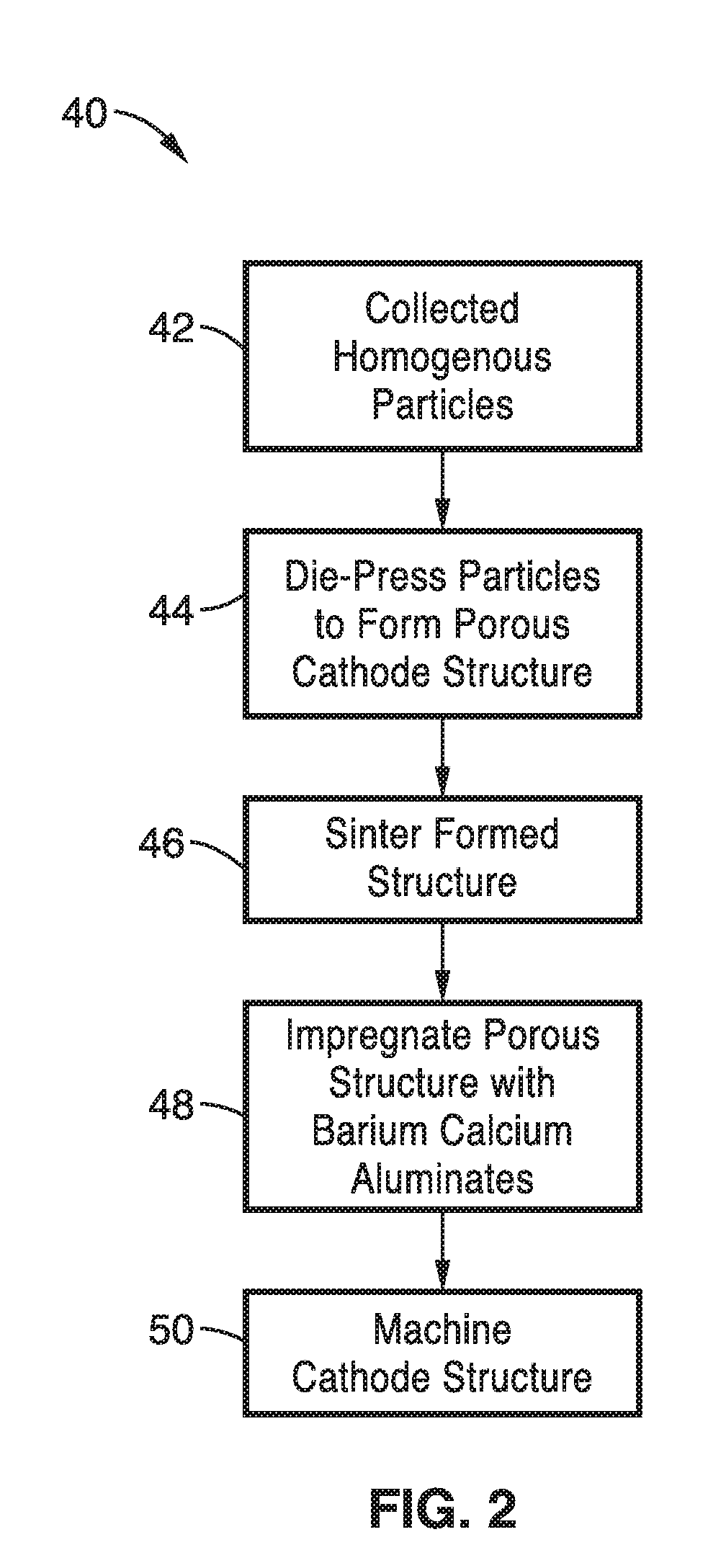
[0088]To illustrate the electron beam emission characteristics of the structure, a microcomposite scandate dispenser cathode was prepared and evaluated. The prepared porous tungsten scandate pellets were impregnated with barium-calcium-aluminates with a molar ratio of 4:1:1. This resulted in the filling of the pores of the tungsten matrix with emission materials.

[0089]Initially, the barium nitrate / Ba(NO3)2, calcium nitrate / Ca(NO3)2 and aluminium nitrate hydrate / Al(NO3)3*XH2O starting materials were prepared in the proper molar ratios. The starting impregnation materials (5.115 grams of barium nitrate, 1.1505 grams of calcium nitrate and 3.659 grams of aluminum nitrate hydrate) were added to 180 mL of deionized water in a 500 mL beaker to produce a solution. The solution was stirred at 200 RPM's to dissolve and mix things thoroughly.

[0090]An ammonium carbonate (CH8N2O3) solution was added dropwise to the solution of impregnation materials while stirring the solution until a precipita...


PUM

PropertyMeasurementUnit
porosityaaaaaaaaaa
porosityaaaaaaaaaa
temperatureaaaaaaaaaa

Abstract

Methods for fabricating refractory metal scandate nanocomposite powders with homogeneous microstructured refractory metal grains and a uniform nanosized dispersion of scandia are provided. The powders prepared by the sol-gel methods have a spherical morphology, a narrow distribution of particle sizes and a very uniform dispersion of nanosized scandia particles joined to the tungsten grains. The powder particle sizes can range from nanometers to micrometers. The powders can be pressed into porous cathode structures that can be impregnated with emissive materials to produce high current density and long life cathodes for high-power terahertz vacuum electron devices. The sol-gel fabrication methods allow control over the materials, particle size, particle composition and pore size and distribution of the cathode structure by manipulation of the process parameters.

Description

CROSS-REFERENCE TO RELATED APPLICATIONS[0001]This application is a 35 U.S.C. §111(a) continuation of PCT international application number PCT / US2016 / 017198 filed on Feb. 9, 2016, incorporated herein by reference in its entirety, which claims priority to, and the benefit of, U.S. provisional patent application Ser. No. 62 / 114,482 filed on Feb. 10, 2015, incorporated herein by reference in its entirety. Priority is claimed to each of the foregoing applications.[0002]The above-referenced PCT international application was published as PCT International Publication No. WO 2016 / 0130580 on Aug. 18, 2016, which publication is incorporated herein by reference in its entirety.STATEMENT REGARDING FEDERALLY SPONSORED RESEARCH OR DEVELOPMENT[0003]This invention was made with Government support under Grant No. G8U543366 awarded by DARPA; Grant Nos. N00164-06-D-8958 and N66001-11-C-2003 awarded by DOD / MTO / DARPA; and Grant Nos. FA9550-04-0101 and FA9550-04-1-0353, awarded by the USAF / AFSOR. The Gov...

Claims


Application Information

Patent Timeline
Patent Type & Authority Applications(United States)
IPC IPC(8): H01J1/146C04B35/50C01G41/00C04B35/626C04B35/64C04B35/624H01J9/04
CPCH01J1/146C04B35/624C04B35/50H01J9/04C04B35/62655C04B35/64C04B35/6261C04B35/6268C01G41/006C04B2235/96C04B2235/5454C04B2235/3222C04B2235/326C04B2235/3208C04B2235/3224C01P2004/64C01P2006/40C04B2235/3215H01J1/142
Inventor LUHMANN, JR., NEVILLE C.SOEKLAND, GORDONGAMZINA, DIANALI, NA
Owner RGT UNIV OF CALIFORNIA
Why Eureka
Try Eureka