Laminate production method

Active Publication Date: 2017-12-14
INTEL CORP
View PDF5 Cites 3 Cited by
  • Summary
  • Abstract
  • Description
  • Claims
  • Application Information

AI Technical Summary

Benefits of technology

[0016]The manufacturing method of the present invention can provide a laminate body with excellent heat resistance (solder heat resistance, for example) a

Problems solved by technology

However, with the technique in Patent Document 1, when thermal curing is performed on the resin composition in a condition attached to a supporting body such as a supporting base film, heating is insufficient in the case of peeling the supporting body after thermal curing, and the cured resin after thermal curing may have inferior heat resistance.
On the other hand, when thermal curing is performed on the resin composition in a condition attached to the supporting body, if curing conditions are relatively severe (such as increased curing temperature or increased curing time), removing resin residue in the via hole is difficult, and there is a problem where the via hole has inferior conduction reliability.
As a result of extensive studies, the inventors discovered that with the method of manufacturing the laminate

Method used


Image

  • Laminate production method

Examples


synthesis example 1

[0157]As a first stage of polymerization, 35 molar parts of 5-ethylidene-bicyclo [2.2.1]hepta-2-en, 0.9 molar parts of I-hexene, 340 molar parts of anisole, and 0.005 molar parts of ruthenium 4-acetoxybenzylidene (dichloro) (4,5-dibromo-1,3-dimesityl-4-imidazolin-2-ylidene) (tricyclohexylphosphine) (C1063, manufactured by Wako Pure Chemical Industries) were incorporated in a nitrogen substituted pressure resistant glass reactor, and polymerization reaction was performed by stirring at 80° C. for 30 minutes to obtain a solution of a norbornene-based ring-opening polymer.

[0158]Next, as a second stage of polymerization, 45 molar parts of tetracyclo [6.5.0.12,5.08,13]trideca-3,8,10,12-tetraene, 20 molar parts of bicyclo [2.2.1] hept-2-ene-5,6-dicarboxylic anhydride, 250 molar parts of anisole, and 0.01 molar parts of C1063 were added to the solution obtained in the first stage of polymerization, and polymerization reaction was performed by stirring at 80° C. for 1.5 hours to obtain a so...

example 1

Preparation of the First Thermosetting Resin Composition

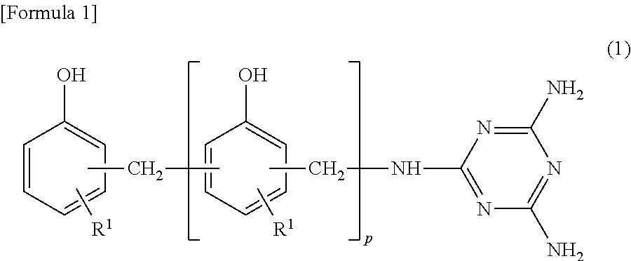
[0161]50 parts of a biphenyldimethylene skeleton novolak epoxy resin as the polyvalent epoxy compound (A) having a biphenyl structure (trade name “NC-3000L”, manufactured by Nippon Kayaku Co., Ltd., epoxy equivalent of 269), 50 parts of tetrakis hydroxyphenylethane type epoxy compound as the epoxy group (B) containing a trivalent or higher polyvalent glycidyl group (trade name “jER1031S”, manufactured by Mitsubishi Chemical Corporation, epoxy equivalent of 200, softening point of 90° C.), 30 parts (15 parts in terms of cresol novolac resin containing a triazine structure) of cresol novolak resin containing a triazine structure as the phenol resin (C) containing a triazine structure (trade name “phenolite LA-3018-50P”, propylene glycol monomethyl ether solution with a nonvolatile content of 50%, manufactured by DIC Corporation, active hydroxyl group equivalent of 154), 115.3 parts (75 parts in terms of active ester compounds) of...

example 2

[0181]Other than changing the heating temperature from 200° C. to 160° C. in the second heating step, the same conditions were applied as 1 to obtain a cured composite and a multilayer printed wiring board, and evaluation was performed in the same way. The results are shown in Table 1.


PUM

PropertyMeasurementUnit
Temperatureaaaaaaaaaa
Diameteraaaaaaaaaa
Electrical conductoraaaaaaaaaa

Abstract

To provide a method for manufacturing a laminate body with excellent heat resistance (solder heat resistance, for example) and excellent conduction reliability in which a small diameter via hole can be formed. RESOLUTION MEANS To provide a manufacturing method of a laminate body, containing: a step of forming onto a supporting body a curable resin composition layer formed from a thermosetting resin composition to obtain a curable resin composition layer with a supporting body; a step of laminating the aforementioned curable resin composition with a supporting body onto a substrate on a curable resin composition layer forming surface side to obtain a pre-cured composite with a supporting body formed from a substrate and a curable resin composition layer with a supporting body; a step of performing a first heating of the aforementioned composite and thermally curing the aforementioned curable resin composition layer to form a cured resin layer to obtain a cured composite with a supporting body formed from a substrate and a cured resin layer with a supporting body; a step of performing hole punching from the aforementioned supporting body side of the aforementioned cured composite with a supporting body to form a via hole in the aforementioned cured resin layer; a step of peeling the aforementioned supporting body from the aforementioned cured composite with a supporting body to obtain a cured composite formed from a substrate and a cured resin layer a step of removing resin residue in the via hole of the aforementioned cured composite; a step of performing a second heating of the aforementioned cured composite; and a step of forming a conductor layer on an inner wall surface of the via hole of the aforementioned cured composite and on the aforementioned cured resin layer.

Description

TECHNICAL FIELD[0001]The present invention relates to a method of manufacturing a laminate body wherein a conductor layer and a cured resin layer are provided on a substrate.BACKGROUND ART[0002]Along with pursuing downsizing, multifunctionalization, increasing communication speeds, and the like of electronic equipment, further densification of the circuit board used in electronic equipment is required, and multilayering of circuit boards is being achieved to meet the requirements of densification. The multilayer circuit board is formed, for example, on an inner layer substrate made of an electrical insulating layer and a conductor layer formed on a surface of the electrical insulating layer, by laminating an electrical insulating layer and forming a conductor layer on the electrical insulating layer, and further repeating laminating the electrical insulating layers and forming the conductor layers.[0003]As a method of manufacturing the laminate body for forming the multilayer circui...

Claims


Application Information

Patent Timeline
IPC IPC(8): H05K3/42H05K3/46H05K3/00
CPCH05K3/429H05K3/0014H05K3/005H05K3/007H05K2203/0723H05K3/422H05K3/423H05K3/4644H05K2203/072H05K3/0055H05K3/0032H05K3/427H05K2203/1105B32B15/08H05K3/18H05K3/42
Inventor FUJIMURA, MAKOTOTATEISHI, YOUHEI
Owner INTEL CORP
Why Eureka
Try Eureka