
Eutectic colloidal crystal, eutectic colloidal crystal solidified body, and methods for producing them

a technology which is applied in the field solidified body of eutectic colloidal crystal, and methods for producing them. it can solve the problems of difficult application to optical devices such as photonic materials, and achieve the effects of improving mechanical strength, easy handling and easy production

Active Publication Date: 2017-12-21
NAGOYA CITY UNIVERSITY
View PDF1 Cites 15 Cited by
  • Summary
  • Abstract
  • Description
  • Claims
  • Application Information

AI Technical Summary

Benefits of technology

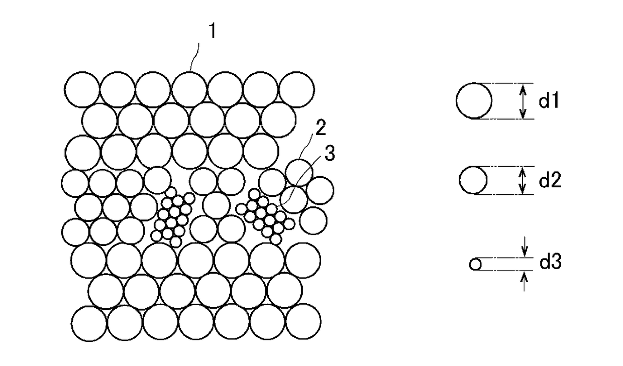
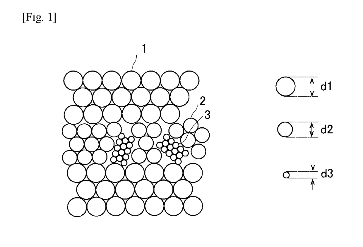
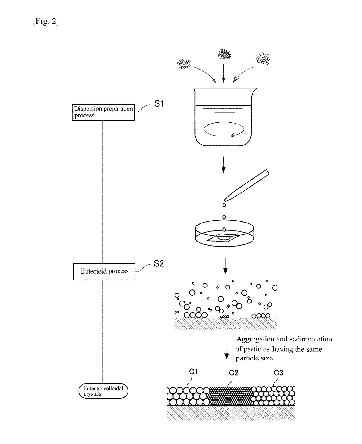
The present invention relates to a new type of colloidal crystal that can be used as a coloring material. This colloidal crystal is made up of two or more kinds of opal-type colloidal crystals that have different lattice constants. By mixing these colloidal crystals together at fixed positions, the diffraction color can be controlled. This colloidal crystal is also resistant to color fading because it does not contain dyes. Additionally, the colloidal crystal can be solidified using an immobilizing agent to improve its mechanical strength. The method for producing this colloidal crystal solidified body involves preparing a colloidal dispersion, depositing different colloidal crystals, and then immobilizing them using photoirradiation. These technical effects make this colloidal crystal a promising coloring material with improved handling and stability.

Problems solved by technology

However, for the opal-type colloidal crystals, only an aggregate composed of colloidal crystals having one lattice constant has been obtained, and there is no report on a eutectic colloidal crystal containing two or more kinds of colloidal crystals composed of monodispersed colloidal particles.
Therefore, the direction of the optical axis of the colloidal crystals can be varied by Brownian movement, and thus the application to optical devices such as photonic materials is difficult.

Method used


Image

  • Eutectic colloidal crystal, eutectic colloidal crystal solidified body, and methods for producing them
  • Eutectic colloidal crystal, eutectic colloidal crystal solidified body, and methods for producing them
  • Eutectic colloidal crystal, eutectic colloidal crystal solidified body, and methods for producing them

Examples


example 1

[0058]In Example 1, a eutectic colloidal crystal was made using three kinds of monodispersed polystyrene particles. More specifically, the first polystyrene particles were spherical charged polystyrene particles PS600 (Thermo Scientific, purchased in the form of an aqueous dispersion with diameter d=600 nm and volume fraction=0.05, coefficient of variation in particle size: 3%), the second polystyrene particles were spherical green fluorescent charged polystyrene particles G500 (commercial product, diameter d=500 nm, volume fraction=0.1, coefficient of variation in particle size: 5%), and the third polystyrene particles were spherical red fluorescent charged polystyrene particles DR390 (commercial product, diameter d=about 390 nm, volume fraction=0.01, coefficient of variation in particle size: 5%). These particles were purified by a dialysis method and an ion exchange method, mixed at the ratio of the first polystyrene particles: second polystyrene particles: third polystyrene part...

example 2

[0060]In Example 2, a eutectic colloidal crystal was made using two kinds of monodispersed polystyrene particles. More specifically, the first polystyrene particles were spherical charged polystyrene particles PS200 (Thermo Scientific, diameter d=200 nm, volume fraction=0.1, coefficient of variation in particle size: 5%), and the second polystyrene particles were spherical charged polystyrene particles PS250 (synthesized by the inventors, diameter d=250 nm, volume fraction=0.068, coefficient of variation in particle size: 15%).

[0061]The polystyrene particles were synthesized by a soap free emulsion polymerization method. More specifically, 210 mL of water, 100 mL of methanol, 20 mL of styrene monomer, 0.15 g of sodium p-styrenesulfonate as an anionic comonomer, and 1 mL of divinylbenzene were mixed, and stirred for about 30 minutes in a constant temperature bath at 80° C., at a rotation speed of 300 rpm, and in an argon atmosphere. Thereafter, 0.1 g of potassium peroxodisulfate as a...

example 3

[0064]In Example 3, a eutectic colloidal crystal was made using three kinds of monodispersed polystyrene particles. More specifically, the first polystyrene particles were spherical charged polystyrene particles PS200 (Thermo Scientific, diameter d=200 nm, volume fraction=0.1), the second polystyrene particles were spherical charged polystyrene particles PS250 (synthesized by the inventors (the particles used in Example 2), diameter d=250 nm, volume fraction=0.068), and the third polystyrene particles were spherical charged polystyrene particles PS300 (Thermo Scientific, diameter d=about 300 nm, volume fraction=0.1, coefficient of variation in particle size: 3%). These particles were purified by a dialysis method and an ion exchange method, mixed at the ratio of the first polystyrene particles:second polystyrene particles:third polystyrene particles=4:3:5 (volume ratio) (100 μL in total), further 200 μL of a 0.1 w % sodium polyacrylate PAANa (molecular weight:one million, degree of ...


PUM

PropertyMeasurementUnit
particle sizeaaaaaaaaaa

Abstract

[Object] Provided are a “eutectic colloidal crystal” which is an aggregate of plural kinds of colloidal crystals having different lattice constants, a solidified body of the eutectic colloidal crystal, and methods for producing them.[Resolution means] The eutectic colloidal crystal of the present invention contains two or more kinds of colloidal crystals composed of substantially monodispersed colloidal particles having different particle sizes. This eutectic colloidal crystal is obtained by providing a colloidal dispersion of two or more kinds of colloidal particles having different particle sizes, and a polymer which will not substantially adsorb to the colloidal particles (the coefficient of variation in particle size of these colloidal particles is less than 20%) dissolved in a dispersion medium (dispersion preparation process), and allowing the colloidal dispersion to stand (eutectoid process).

Description

TECHNICAL FIELD[0001]The present invention relates to an aggregate of two or more kinds of opal-type colloidal crystals which are composed of monodispersed colloidal particles and mixed together at fixed positions (hereinafter referred to as “eutectic colloidal crystal” in this description), a solidified body of the eutectic colloidal crystal, and methods for producing them.BACKGROUND ART[0002]Colloid means a system in which disperse phases having a size of about several nm to several μm (e.g., colloidal particles) are dispersed in a dispersion medium. The colloidal particles in the colloid can be arranged regularly to form an orderly structure under special conditions, which is called colloidal crystals.[0003]Similarly to usual crystals, the colloidal crystals Bragg-diffract electromagnetic waves according to the lattice spacing. The diffraction wavelength can be set to a visible light range by selecting production conditions (e.g., particle concentration, particle diameter, and re...

Claims


Application Information

Patent Timeline
Patent Type & Authority Applications(United States)
IPC IPC(8): B01J13/00C08L25/06
CPCB01J13/0065C08L25/06C08L2205/18C08L2205/03C08L2205/025C08F257/02C08F222/385
Inventor YAMANAKA, JUNPEITOYOTAMA, AKIKOOKUZONO, TOHRUUDA, SATOSHINOZAWA, JUN
Owner NAGOYA CITY UNIVERSITY
Learn More