Fabrication method of print head for multiplex chemotyping microarray

a technology of chemotyping microarray and print head, which is applied in the direction of material analysis using wave/particle radiation, laboratory glassware, instruments, etc., can solve the problems of limiting data analysis with respect to wavelength, and affecting the quality of sample preparation, so as to reduce manufacturing time, save time and energy, and prevent the breakdown of silicon nitride membrane. , the effect of reducing the manufacturing tim

Active Publication Date: 2017-12-28
KOREA INST OF SCI & TECH
View PDF3 Cites 3 Cited by
  • Summary
  • Abstract
  • Description
  • Claims
  • Application Information

AI Technical Summary

Benefits of technology

[0010]The present disclosure is devised to improve application possibility of multiplex chemotyping microarray (MCM) device that includes the print head, and is directed to provide a fabrication method of the print head capable of reducing manufacturing cost and operating cost by simplifying the fabrication method of the print head.
[0021]A fabrication method of the print head according to the present invention irradiates the ultraviolet only to any one side of the top surface or the bottom surface of the silicon wafer, thereby having advantages of not only reducing manufacturing time compared to the conventional fabrication method that irradiates both the top surface and the bottom surface of the silicon wafer but also skipping backside alignment which is regarded as the most difficult process.
[0022]Also, ultraviolet energy needed for irradiation of the ultraviolet and one step of RIE (Reactive Ion Etching) decreases, thereby saving operating cost thereof, time, and energy.
[0023]In addition, in the fabrication method of the print head, there is an effect of preventing breakdown of silicon nitride membrane because sample droplet storage space is completely opened and reducing manufacturing cost compared to the conventional fabrication method that prepares a separate photomask to form sample droplet storage space and droplet opening because only one photomask is needed for forming sample droplet storage space.

Problems solved by technology

The quality and accuracy of measurements of materials, however, critically affected by the quality of sample preparation.
Also, as an obstacle to high efficiency FTIR sampling, restrictive depth of penetration may be considered.
Actually, in the case of leaves or stems without any process, only epidermal cells forming outside of plant cells are observed, therefore there is a limit regarding data analysis with respect to wavelength.
Also, ultraviolet energy needed for irradiation of the ultraviolet and one step of RIE (Reactive Ion Etching) decreases, thereby saving operating cost thereof, time, and energy.

Method used


Image

  • Fabrication method of print head for multiplex chemotyping microarray
  • Fabrication method of print head for multiplex chemotyping microarray
  • Fabrication method of print head for multiplex chemotyping microarray

Examples


exemplary embodiment 1

nt Head (see FIGS. 5 and 6)

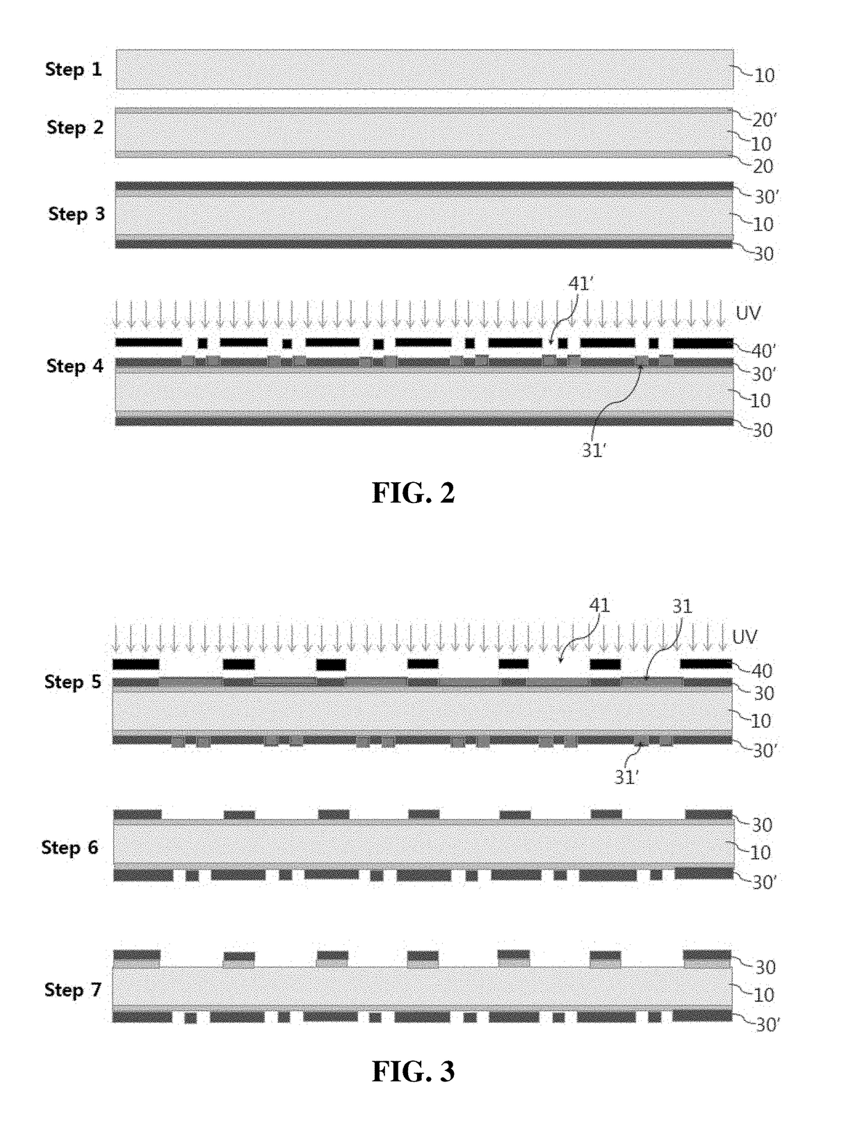
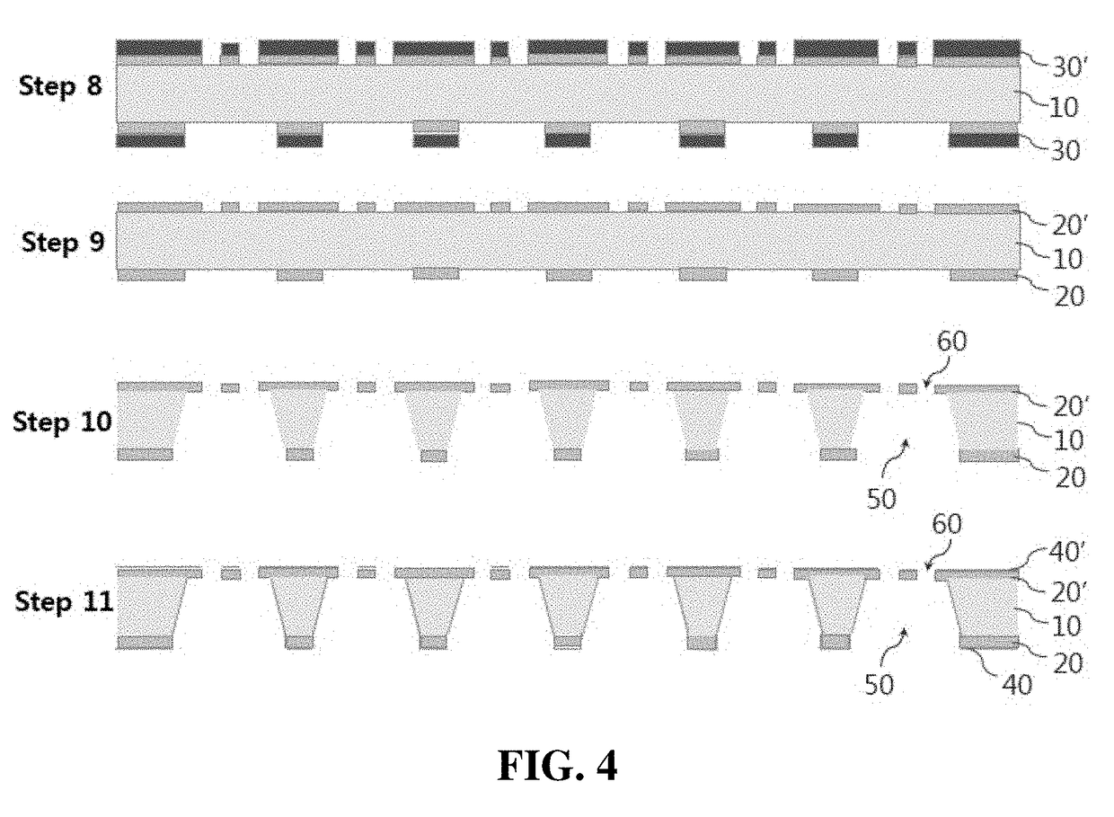
[0058]Step 1: Preparing the Silicon Wafer

[0059]The silicon wafer 10 washed by piranha solution is used as materials of the print head. Here, the wafer may have about 500-600 μm of thickness and 4 to 6 inches of diameter.

[0060]Step 2: Stacking the Silicon Nitride Films 20 and 20′ to the Top Side and the Bottom Side of the Silicon Wafer

[0061]Silicon nitride films 20 and 20′ having 50-400 nm of thickness with low stress are stacked up front side and back side of the silicon wafer 10 provided at step 2, and as a stacking method, Low-pressure CVD (LPCVD) was used.

[0062]Step 3: Coating with the Photoresists to the Top Side and the Bottom Side of the Silicon Wafer

[0063]After spin coating with the photoresists 30 and 30′ to the top side and the bottom side of the wafer 10 that silicon nitride film 20 and 20′ are stacked, and are dried by heating at about 90° C. for 1 minute to 5 minutes.

[0064]Step 4: Irradiating the Ultraviolet Light to the Top Side or the Bottom ...

exemplary embodiment 2

he Bioenergy Crops Using MCM (see FIG. 7)

[0079]Step 1: Preparing Hydrophobic Infrared Light Penetrative / Reflective Substrate for Printing Sample Particle-Dispersed Liquid

[0080]Hydrophobic property of surface of the infrared penetrative / reflective substrate is an essential condition for successful sample printing. In order to increase the hydrophobic property, single molecule FOTS layer is deposited on surface of the substrate by MOCVD (Metal-Organic Chemical Vapor Deposition) method.

[0081]Step 2: Preparing Dispersed Liquid of the Bioenergy Crop Particles

[0082]After grinding bioenergy crop (Brachypodium distachyon) into equal to or less than 100 μm by ball milling, it is dispersed evenly to the liquid (water, buffer fluid).

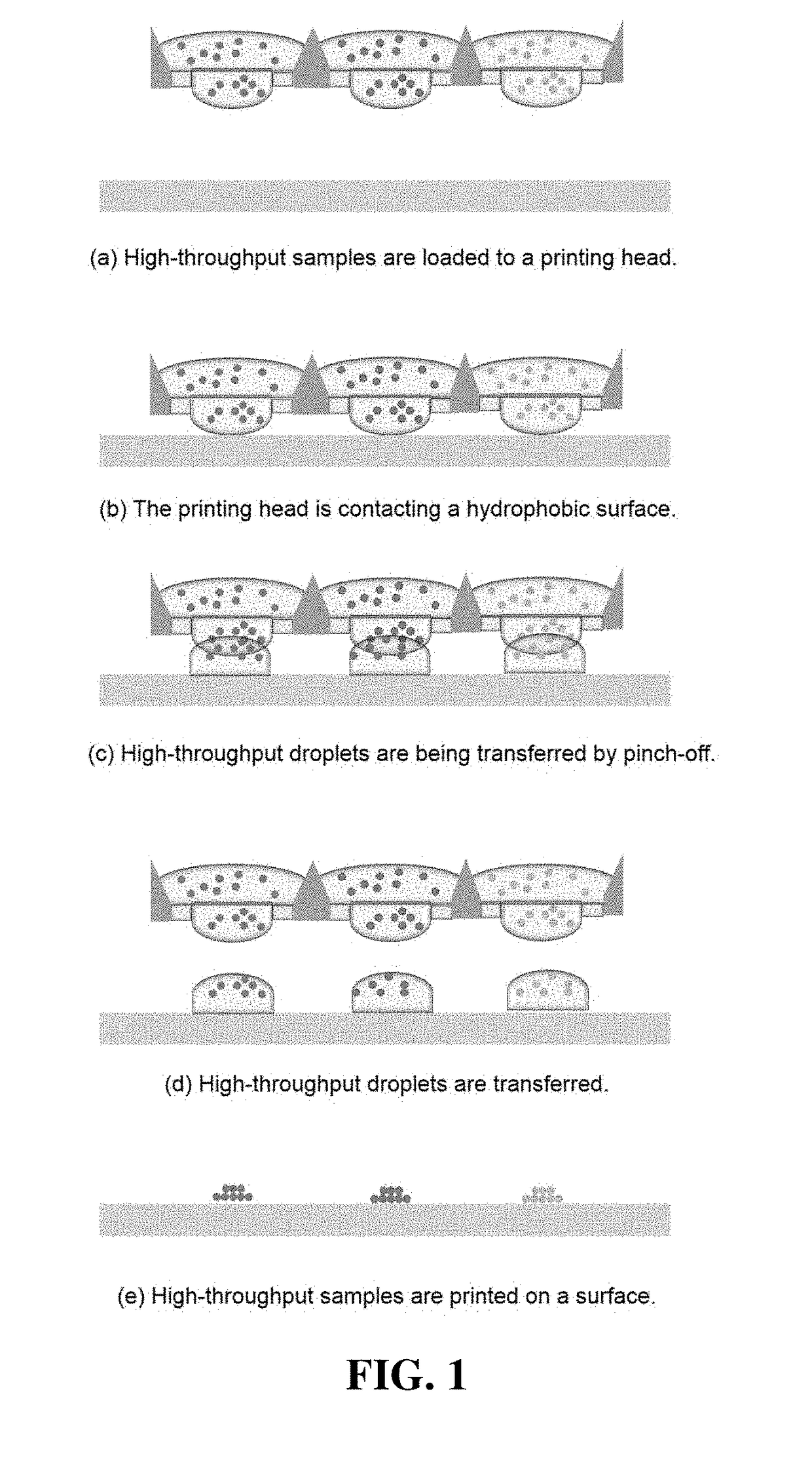
[0083]Step 3: Printing the Bioenergy Crop Particle Dispersed Liquid on Infrared Light Penetrative / Reflective Substrates

[0084]After the bioenergy crop particle dispersed liquid is injected to the storage in the print head within a range of 1-100 uL, and is printed o...


PUM


Abstract

Provided is a fabrication method of print head of MCM device formed micro patterned air gap capable of picoliter-scale droplet printing, and more particularly, is characterized in that comprising preparing silicon wafer 10 washed by piranha solution at step A, stacking silicon nitride films 20 and 20′ up front surface and back surface of prepared silicon wafer at step B, drying after applying photoresists 30 and 30′ to top surface and bottom surface of the silicon nitride film 20 and 20′ at step C, removing partially the photoresists through pre-determined pattern by irradiation of ultraviolet after arranging photomask 40 formed through pre-determined pattern in any one side of the photoresists 30 and 30′ at step D, forming sample droplet storage space opening by removing silicon nitride film 21 contacted to photoresists removed by pre-determined pattern at step E, removing the photoresists 30 and 30′ stacked up the silicon nitride film 20 and 20′ at step F, forming sample droplet storage space 50 by etching the silicon wafer at step G, and forming sample droplet opening 60 by irradiating ultrasonic waves at step H.

Description

FIELD[0001]The present invention relates to a MCM (multiplex chemotyping microarray) device, and more particularly, to a fabrication method of the MCM device formed with silicon based micropatterned air gap capable of picoliter-scale droplet printing.DESCRIPTION OF THE RELATED ART[0002]Technology for producing bioenergy using lignocellulosic biomass has attracted great attention in recent years. The increased promise of developing cost-effective bioenergy solutions from lignocellulosic biomass has brought the generation of tens of thousands of natural and induced variations in energy crops weekly, and a widespread need of rapid and high throughput and large scale analytical methods to screen for the promising ones.[0003]One common analytical technology is use of mid-or / and near-infrared spectroscopy to identify, to quantify, and to assay the plant cell wall composition of the plant starting as well as ending materials. The quality and accuracy of measurements of materials, however, ...

Claims


Application Information

Patent Timeline
Patent Type & Authority Applications(United States)
IPC IPC(8): B01J19/00B41J2/16
CPCB01J19/0046B41J2/1626B41J2/162B01J2219/00759B01J2219/00385B01J2219/00612B01J2219/0074B01J2219/00587B01J2219/0038B01L3/0262B01L2200/12B01L2300/0819B01L2300/0893B41J2/1629B41J2/1639B81C2201/0184G01N1/28G01N33/00G01N33/0098G01N2223/345
Inventor CHOI, SUNPARK, CHAN HYUKLEE, YOUNG HAENG
Owner KOREA INST OF SCI & TECH
Why Eureka
Try Eureka