
Composite implant material

a composite implant and implant technology, applied in the field of implantable prosthetic devices, can solve the problems of affecting the diagnosis of potentially life-threatening diseases, requiring significant sensitivity and skill of mammographers, and affecting the examination of augmented breasts, so as to improve radiology characteristics, reduce associated visual noise, and improve radiolucency

Active Publication Date: 2018-01-04
G & G BIOTECH
View PDF2 Cites 2 Cited by
  • Summary
  • Abstract
  • Description
  • Claims
  • Application Information

AI Technical Summary

Benefits of technology

The patent describes an implant material that has improved ultrasound image quality and reduced visual noise. The material is easily recognizable and can be distinguished from other materials. The material also reduces the bleed of free molecules, reducing the risk of complications. The implant material is reinforced, meaning it is stronger and better able to withstand rupture or degradation. The material is shaped to provide a specific shape and maintain it for a lifetime, feels like natural tissue, and is safe and compatible with the human body. In summary, the patent describes a new implant material that has improved image quality, reduced bleed of free molecules, and improved strength and shape-maintenance.

Problems solved by technology

Prior art implants present challenges in several areas which are described in more detail below including: imaging, such as mammograms; gel bleed from the implant; and mechanical and chemical issues.
Therefore diagnosis of potentially life-threatening diseases is hampered by the prior art implants which are radiopaque.
This theoretically allows better imaging of the front part of each breast but typically, 30% of breast tissue can still be obscured by the implant;It is a complex technique that requires significant sensitivity and skill by mammographers.
They can be uncomfortable in women who have had hard scar tissue form around the implants (capsular contractures);The patient is exposed to double the amounts of radiation of a normal mammography.Examination of the augmented breasts is more time consuming;Patients exhibit extensive anxiety about implant damage from the compression process.
Reverberations from the gel create visual noise on the picture which interferes with the ability of the radiologist to detect abnormalities.
Silicone has a conduction speed of approximately 997 m / sec and the slowing of the sound waves in the implant is what causes many of the reverberations and artifacts seen.
However, due to its anechoic nature and high resemblance to water, free silicone gel can often be mistaken for a pathology such as a cyst.
The background art therefore does not teach or suggest a prosthetic implant material that does not obscure the tissues under examination or interfere with the chosen imaging technique.
Further, as shown, prior art implants cause visual noise that interferes with the ability of the radiologist to detect abnormalities.
A further problem with prior art implants is gel bleed from an intact implant.
It is undesirable to have silicone bleed into bodily tissues as the free silicone can elicit a foreign body response resulting in granulomas and calcifications in the breast which can be misinterpreted in radiological screenings as breast tissue abnormalities.
Free silicone can also easily migrate into the lymphatic system and accumulate in the lymph nodes (usually in the axilla) resulting in lumps and lymphadenopathy.
While these efforts have resulted in 4th and 5th generation breast implants which have somewhat reduced gel bleed, they have not solved the problem completely.
Furthermore, these solutions are only somewhat effective while the implant shell is intact.
When the implant shell is compromised due to rupture or degradation, these solutions provide significantly reduced effectiveness allowing elevated rates of solvent migration into the body.
Often implants suffer from visible folds and wrinkles (especially in women with thin tissue coverage).
Thus increased crosslinking has advantages, however, excessive increases in crosslinking may result in the gel breaking even without externally applied forces because of internal residual stresses.
However, increasing the crosslinker component excessively results in the gel breaking.
In this case, mixing at a ratio of 3:2 results in a highly cohesive gel that breaks and fractures without any applied load.

Method used


Image

  • Composite implant material
  • Composite implant material
  • Composite implant material

Examples


Embodiment Construction

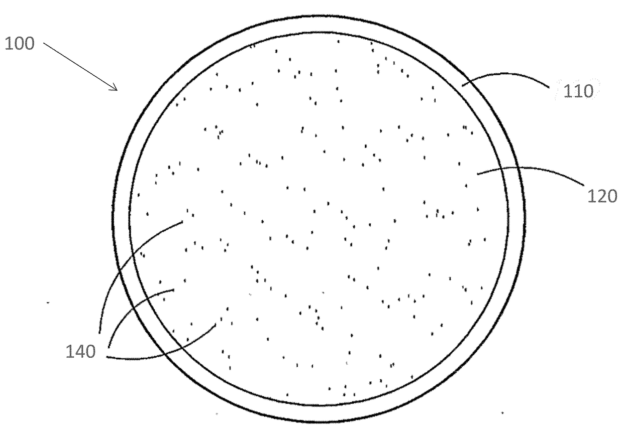
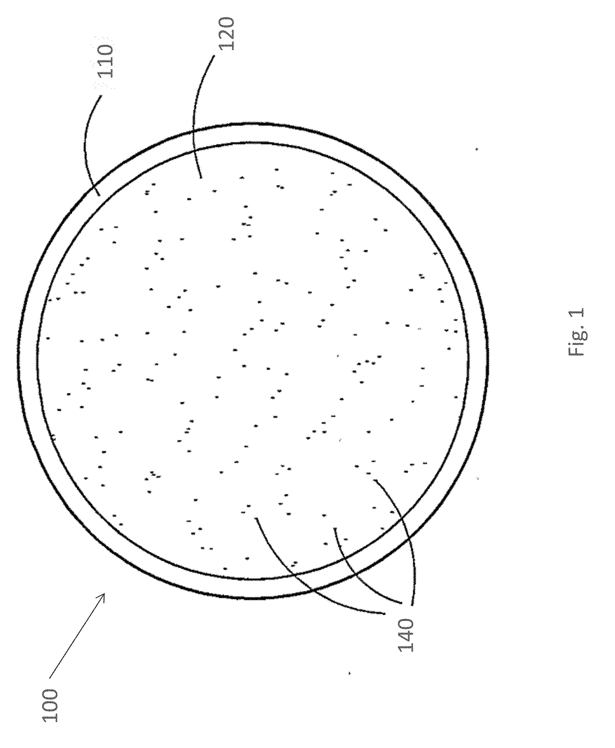
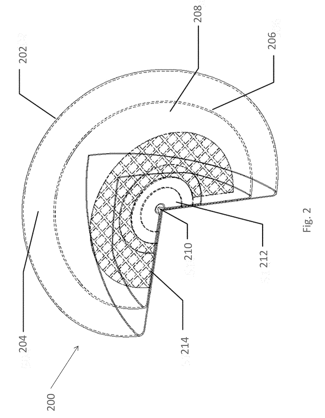
[0098]The present invention provides a composite implant material comprising a base material mixed with additives. The implant material has improved radiology characteristics such as improved radiolucency and decreased associated visual noise from ultrasonography. The definition of the implant shell, when imaged using ultrasound, is preferably improved through use of a composite material immediately adjacent to the shell that is hyperechoic. As echoes are created by the differences in conduction speed of sound waves, hyperechoic implant material is created through the maximum reduction in the speed of sound. The implant therefore preferably comprises low density additives such as hollow additives or additives that include gas. Preferably, the additives have a partial or complete vacuum, making the echo even stronger, as there are less sound conducting molecules.

[0099]The material of the present invention is more radiolucent than pure silicone gel, when viewed for example in a mammog...


PUM

PropertyMeasurementUnit
surface roughnessaaaaaaaaaa
conduction speedaaaaaaaaaa

Abstract

A prosthetic implant with improved properties, suitable for implantation to the human body, comprising a composite comprising a base material and a plurality of additives, wherein the additives are selected from radiolucent additives and / or hyperechoic additives; or wherein the additives are selected to reduce the solvent concentration by between 5%-95%; or wherein the additives are selected to increase the elastic modulus by more than 20%; or wherein the additives are selected for combining these effects.

Description

FIELD OF THE INVENTION[0001]The present invention relates generally to implantable prosthetic devices and specifically to implantable prosthetic devices featuring a composite of a base material and an additive material.BACKGROUND OF THE INVENTION[0002]In the last century reconstructive and cosmetic surgery has become a common practice. Specifically reconstructive breast surgery has been developed to allow reconstruction of a woman's breast that was affected by procedures such as mastectomy. Cosmetic breast surgery has also become available to amend the appearance of a woman's breast, for example by adding an implant to increase the size of the breast, to correct asymmetries, change shape and fix deformities.[0003]The material chosen for the implant must have the appropriate resilience, elasticity and pliability, which provides it with a specific feeling when being sensed. Generally it is desirable to provide an implant which provides a specific shape and mimics the feel of real huma...

Claims


Application Information

Patent Timeline
Patent Type & Authority Applications(United States)
IPC IPC(8): A61L27/50A61L27/18A61F2/12A61B6/00
CPCA61L27/50A61F2/12A61L27/18A61F2210/0076A61B6/502A61F2210/0057A61F2250/0091A61L2430/04A61L27/446A61L27/48A61L27/54A61L2300/44A61F2250/0025A61F2250/0036A61F2250/0098C08L83/04A61L27/42
Inventor GOVREEN-SEGAL, DAELDVIR, HAIMGOVRIN-YEHUDAIN, JACKY
Owner G & G BIOTECH
Learn More