Method for producing catalyst wherein catalyst particles having core/shell structure are supported

a catalyst and core/shell technology, applied in the direction of cell components, sustainable manufacturing/processing, physical/chemical process catalysts, etc., can solve the problems of significant influence of catalyst cost and thereby fuel cell cost, particularly high price of platinum, etc., to achieve excellent balance, efficient manufacturing, and enhanced throughput

Active Publication Date: 2018-02-01
TANAKA PRECIOUS METAL IND
View PDF3 Cites 2 Cited by
  • Summary
  • Abstract
  • Description
  • Claims
  • Application Information

AI Technical Summary

Benefits of technology

[0031]As explained above, the present invention is to optimize the platinum displacement treatment step with respect to a method of manufacturing a catalyst according to the Cu-UPD technique including an electrolytic treatment step and platinum displacement treatment step, thereby relaxing the strict treating conditions in the electrolytic treatment step to achieve an enhanced throughput. According to the present invention, a catalytic particle having a core / shell structure can be efficiently manufactured. Additionally, the catalyst manufactured according to the present invention also exhibits a satisfactory activity, and thus, is excellent in balance between a cost reduction effect due to reduction in the amount of platinum used and improved catalytic performance.

Problems solved by technology

With respect to such catalysts, while catalytic activity is attributable to existence of platinum, platinum is particularly expensive among precious metals, and thus the amount thereof used is to significantly affect the catalyst cost and thereby the fuel cell cost.

Method used


Image

  • Method for producing catalyst wherein catalyst particles having core/shell structure are supported
  • Method for producing catalyst wherein catalyst particles having core/shell structure are supported
  • Method for producing catalyst wherein catalyst particles having core/shell structure are supported

Examples


Embodiment Construction

[0034]The best mode of the embodiment in the present invention will be explained below.

[0035]First Embodiment: in this embodiment, a catalyst containing supported catalytic particle having a core / shell structure where palladium is employed as the core particle was manufactured, and then activity thereof was evaluated. At first, 35 g of carbon powder (trade name: Ketjen Black EC, specific surface area: 800 g / m3), which was to be the carrier of the catalyst, was immersed in a palladium chloride solution (amount of Pd, 15 g (0.028 mol)), then the solution was neutralized with sodium carbonate. The resultant material was subjected to a reduction treatment with sodium formate to produce carbon powder supporting a palladium particle which was to be the core particle.

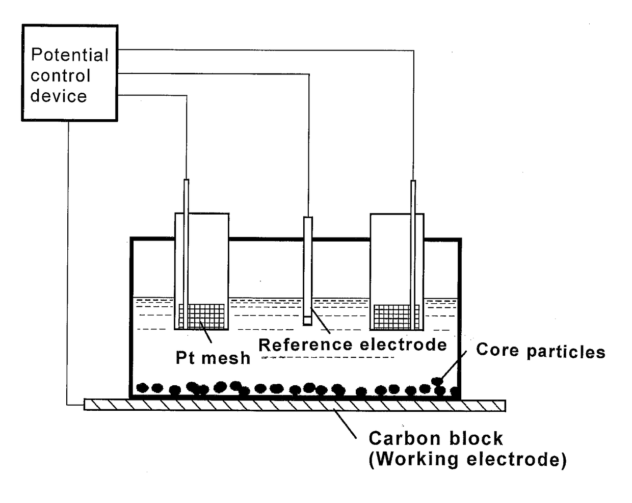
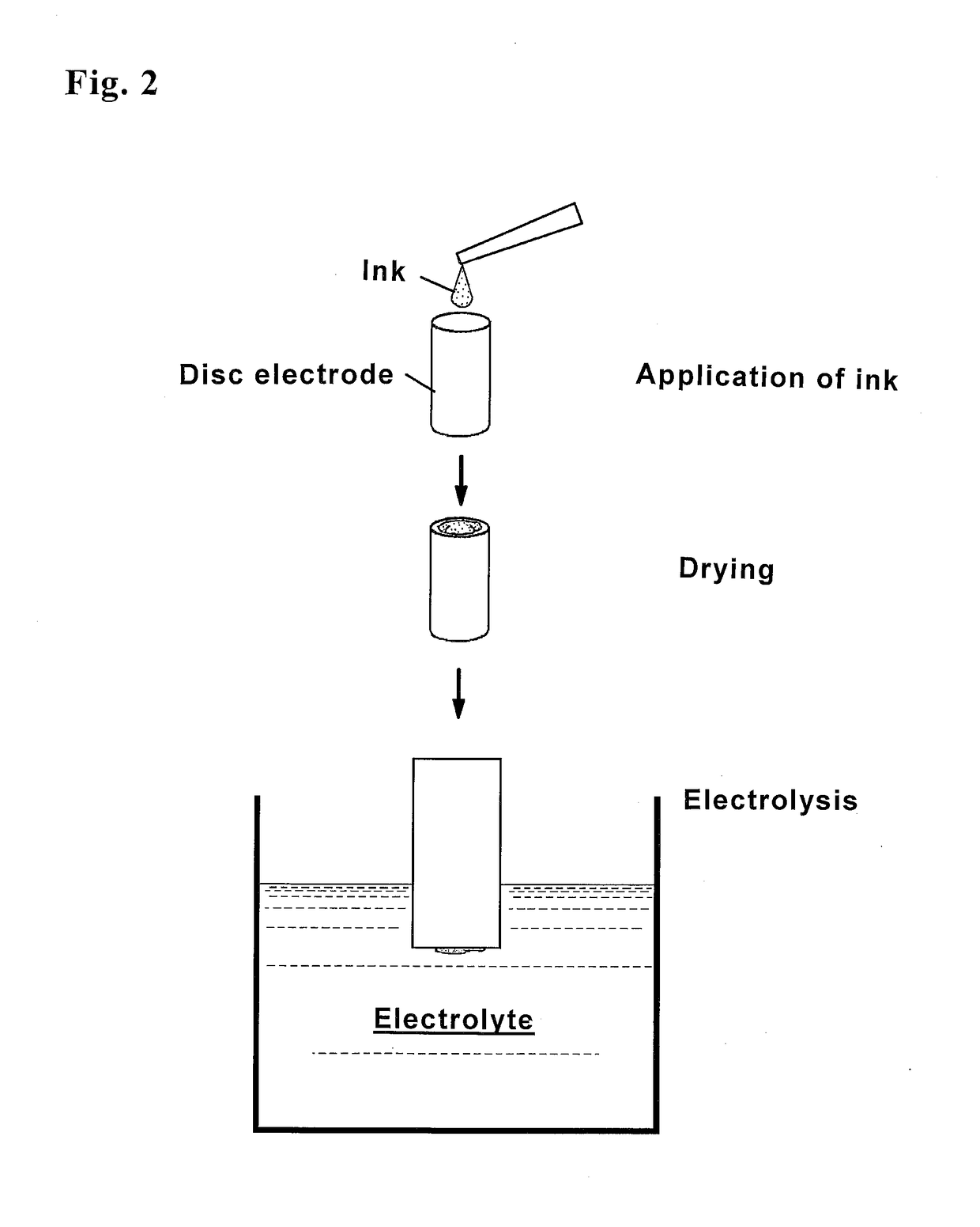
[0036]Subsequently, the palladium particle surface was covered with a copper layer. The electrolysis apparatus used in the present embodiment is shown in FIG. 1. The electrolysis apparatus shown in FIG. 1 is equipped with a co...


PUM

PropertyMeasurementUnit
particle diameteraaaaaaaaaa
timeaaaaaaaaaa

Abstract

A method for forming catalyst particles, each of which has a core/shell structure, by a Cu-UPD method. Namely, a method of manufacturing a catalyst wherein catalyst particles, each of which has a core/shell structure composed of a shell layer that is formed of platinum and a core particle that is covered with the shell layer and is formed of a metal other than platinum, are supported on a carrier. This method is characterized by comprising: an electrolysis step wherein the carrier supporting the core particles is electrolyzed in an electrolytic solution containing copper ions, so that copper is precipitated on the surfaces of the core particles; and a substitution reaction step wherein a platinum compound solution is brought into contact with the core particles, on which copper has been precipitated, so that the copper on the surface of each core particle is substituted by platinum, thereby forming a shell layer that is formed of platinum. This method is further characterized in that the platinum compound solution in the substitution reaction step contains citric acid.

Description

FIELD OF THE INVENTION[0001]The present invention relates to a method of manufacturing a catalyst containing carrier-supported catalytic particles having a core / shell structure comprising a shell layer including platinum and core particles containing a metal other than platinum. In particular, the present invention relates to a method of manufacturing a catalyst which is useful for a catalyst for solid polymer fuel cells, exhibits excellent manufacturing efficiency and also has a satisfactory catalytic activity.DESCRIPTION OF THE RELATED ART[0002]Fuel cells have been highly promising as a next-generation power generation system. In particular, solid polymer fuel cells, employing a solid polymer as an electrolyte, have been desired for use as a power source for electric automobiles because of a lower operational temperature comparing with that of phosphoric acid fuel cells and the like and compactness thereof. A mixture of a catalyst and solid polymer is used as an electrode to promo...

Claims


Application Information

Patent Timeline
Patent Type & Authority Applications(United States)
IPC IPC(8): H01M4/88H01M4/92H01M4/86
CPCH01M4/8878H01M4/8657H01M4/926H01M4/8853H01M2008/1095B01J23/44B01J37/02H01M8/10H01M4/86H01M4/88H01M4/90H01M4/92B01J37/348B01J35/0006B01J35/008Y02E60/50B01J23/42B01J35/0073B01J37/0201C23C18/54C25D3/38H01M4/921C25D21/04Y02P70/50
Inventor MATSUTANI, KOICHIKAIEDA, TAKESHIAKIYAMA, TOMOHIRO
Owner TANAKA PRECIOUS METAL IND
Why Eureka
Try Eureka