Method and Apparatus for Optical Sensing

a technology of optical sensing and optical sensing, applied in the direction of optical detection, converting sensor output, instruments, etc., to achieve the effects of improving the overall sensitivity of the system, broad bandwidth, and low reflectivity

Active Publication Date: 2018-02-15
SILIXA
View PDF5 Cites 33 Cited by
  • Summary
  • Abstract
  • Description
  • Claims
  • Application Information

AI Technical Summary

Benefits of technology

[0004]Embodiments of the invention provide an improved optical fiber distributed acoustic sensor system that makes use of a specially designed optical fiber to improve overall sensitivity of the system, in some embodiments by a factor in excess of 10. This is achieved by inserting into the fiber weak (by which we mean of low reflectivity) broadband reflectors periodically along the fiber. The reflectors reflect only a small proportion of the light from the DAS incident thereon back along the fiber, typically in the region of 0.001% to 0.1%, but preferably around 0.01% reflectivity per reflector. In addition, to allow for temperature compensation, the reflection bandwidth is relatively broadband i.e. equal or greater than the region of +/−2 nm, preferably as large as +/−5 nm from the nominal laser wavelength. This provides for temperature dependent reflectivity of the reflectors to be accommodated, particularly where

Problems solved by technology

These reflections are received at a distributed acoustic sensing system, and are subject to a known delay, to provide

Method used


Image

  • Method and Apparatus for Optical Sensing
  • Method and Apparatus for Optical Sensing
  • Method and Apparatus for Optical Sensing

Examples


first embodiment

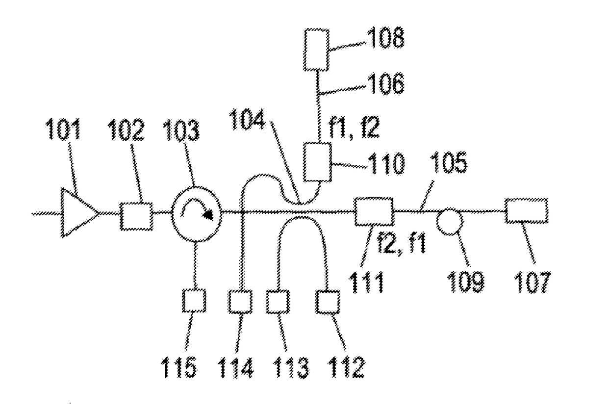
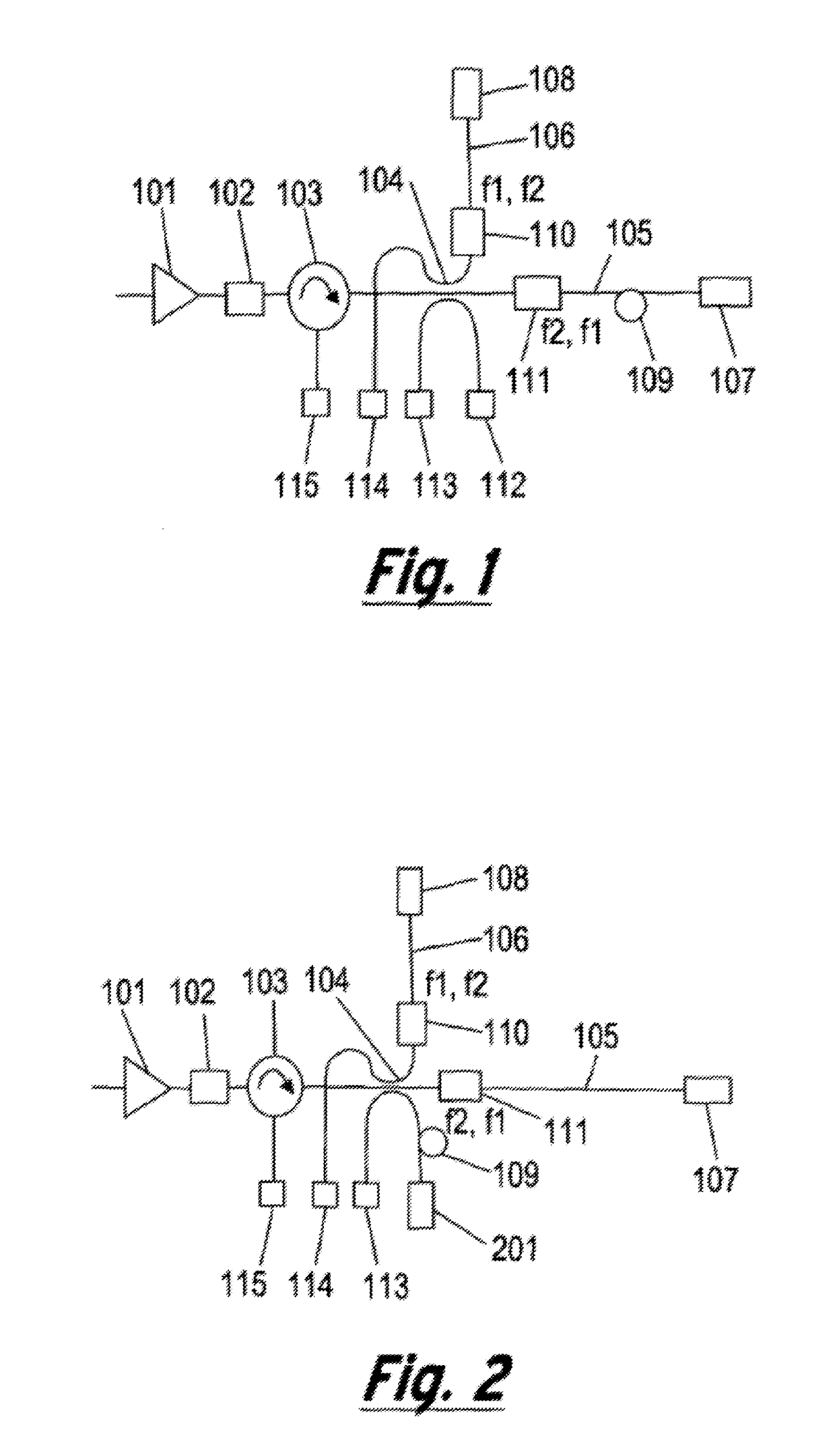
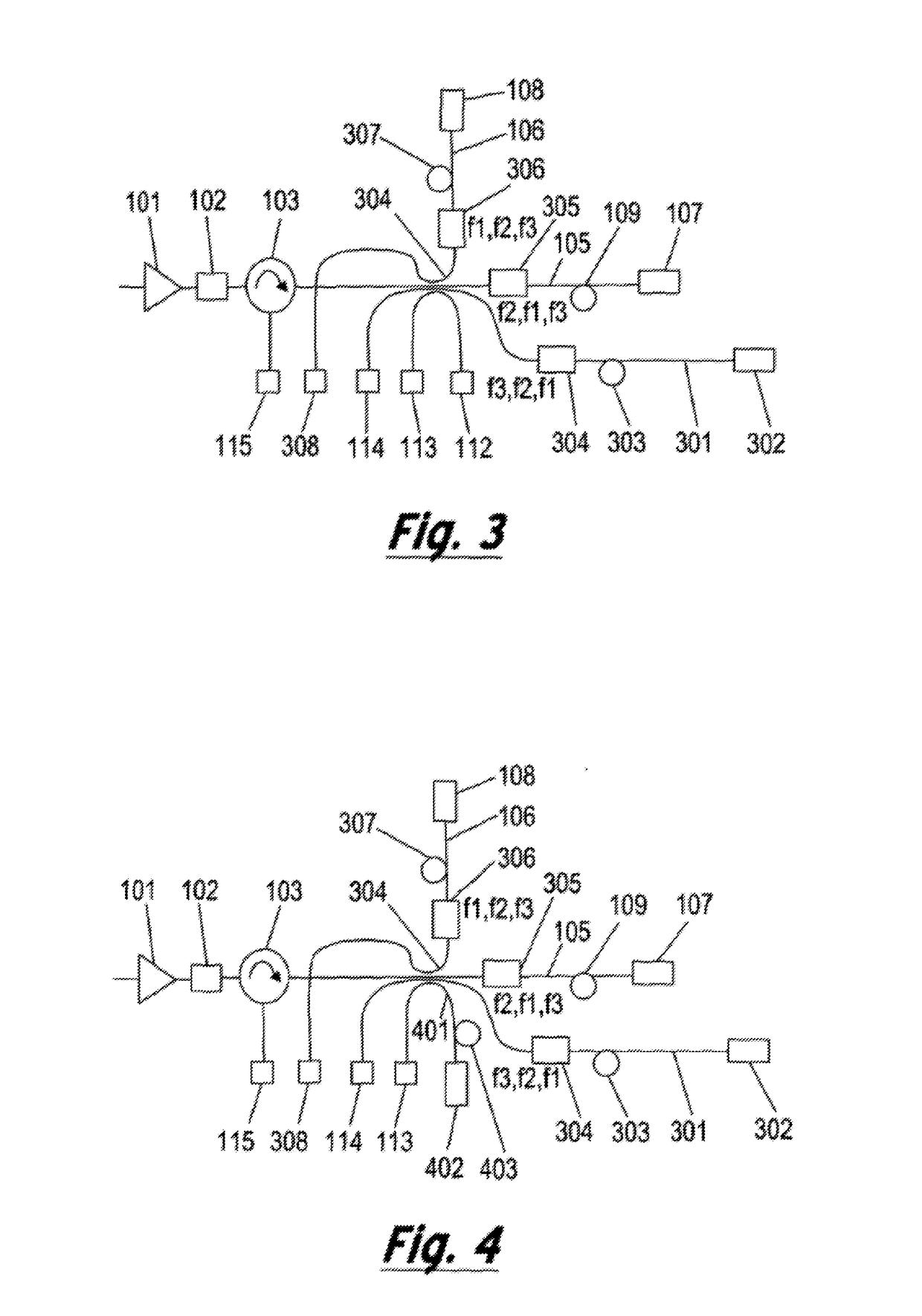
[0048]FIG. 1 shows a first embodiment, generally depicted at 100, of an interferometer for measuring the optical amplitude, phase and frequency of an optical signal. The incoming light from a light source (not shown) is preferably amplified in an optical amplifier 101, and transmitted to the optical filter 102. The filter 102 filters the out of band Amplified Spontaneous Emission noise (ASE) of the amplifier 101. The light then enters into an optical circulator 103 which is connected to a 3×3 optical coupler 104. A portion of the light is directed to the photodetector 112 to monitor the light intensity of the input light. The other portions of light are directed along first and second optical paths 105 and 106, with a path length difference (109) between the two paths. The path length difference therefore introduces a delay into one arm 105 of the interferometer, such that the light that is reflected back for interference at any one time in that arm 105 is from a point closer along ...

embodiment 700

[0055]In this embodiment 700, light emitted by a laser 701 is modulated by a pulse signal 702. An optical amplifier 705 is used to boost the pulsed laser light, and this is followed by a band-pass filter 706 to filter out the ASE noise of the amplifier. The optical signal is then sent to an optical circulator 707. An additional optical filter 708 may be used at one port of the circulator 707. The light is sent to sensing fibre 712, which is for example a single mode fibre or a multimode fibre deployed in an environment in which acoustic perturbations are desired to be monitored. A length of the fibre may be isolated and used as a reference section 710, for example in a “quiet” location. The reference section 710 may be formed between reflectors or a combination of beam splitters and reflectors 709 and 711.

[0056]The reflected and the backscattered light generated along the sensing fibre 712 is directed through the circulator 707 and into the interferometer 713. The detailed operation...


PUM


Abstract

An optical fiber distributed acoustic sensor system includes weak broadband reflectors inserted periodically along the fiber. The reflectors reflect only a small proportion of the light from the DAS incident thereon back along the fiber, typically in the region of 0.001% to 0.1%, but preferably around 0.01% reflectivity per reflector. In addition, to allow for temperate compensation to ensure that the same reflectivity is obtained if the temperature changes, the reflection bandwidth is relatively broadband. In some embodiments the reflectors are formed from a series of fiber Bragg gratings, each with a different center reflecting frequency, the reflecting frequencies and bandwidths of the gratings being selected to provide the broadband reflection. A chirped grating may also be used to provide the same effect. In preferred embodiments, the reflectors are spaced at half the gauge length i.e. the desired spatial resolution of the optical fiber DAS.

Description

TECHNICAL FIELD[0001]Embodiments of the present invention relate to distributed optical fibre sensors, and in particular in some embodiments to such sensors with reflective elements integrated into the sensing optical fiber.BACKGROUND TO THE INVENTION AND PRIOR ART[0002]Optical fiber based distributed sensor systems are finding many applications, in particular in the oil and gas industry for flow monitoring and seismic detection, and in the security industry for area or perimeter security monitoring, or monitoring along a long line such as a pipeline or railway line. The present applicant, Silixa Ltd, of Elstree, London, markets two optical fiber distributed sensing systems, the Silixa® iDAS™ system, which is a very sensitive optical fiber distributed acoustic sensor, and the Silixa® Ultima™ system, which is a distributed optical fiber based temperature sensor. Further details of the iDAS™ system are available at the priority date at http: / / www.silixa.com / technology / idas / , and furth...

Claims


Application Information

Patent Timeline
IPC IPC(8): G01D5/353G01H9/00
CPCG01D5/35374G01H9/004G01D5/35306G01D5/3537G01D5/35316G02B6/02085G01D5/353E21B47/135G01V8/16
Inventor FARHADIROUSHAN, MAHMOUDPARKER, TOMSHATALIN, SERGEY
Owner SILIXA
Why Eureka
Try Eureka