
Planar Thermocatalytic Sensor of Combustable Gases and Vapours

a thermocatalytic sensor and combustible gas technology, applied in the direction of material thermal analysis, instruments, material heat development, etc., can solve the problems of heavy manual labor costs, inability to guarantee, and progressive drop of sensitivity, so as to improve the parameters of sensitive elements, improve the design, and reduce power consumption

Active Publication Date: 2018-05-10
ROSNEFT OIL CO
View PDF1 Cites 2 Cited by
  • Summary
  • Abstract
  • Description
  • Claims
  • Application Information

AI Technical Summary

Benefits of technology

The present invention improves the design of sensitive elements and the thermocatalytic sensor as a whole to increase sensitivity, reduce power consumption, decrease inertance, and improve reproducibility. The sensitive elements have also been made more resistant to catalyst poisoning. The sensor has better stability and resistance to catalyst poisoning. The measuring microheaters are arranged on arms protruding out of the common substrate and process holes are made near them to decrease heat removal and prevent precursors from spreading during deposition. The reaction chamber has a restrictive calibrated orifice to decrease the diffusion flow of the gas mixture. The sensor has a single structure of the sensitive elements with minimized geometric sizes and increased regular pores to ensure a film-wise mode of heat transfer and predominantly molecular diffusion mode in the pores.

Problems solved by technology

However, thermocatalytic sensors have several shortcomings such as an alteration of pore structure of the support in time and, as a consequence, of catalytic activity of the working SE, which both result in a progressive drop of sensitivity and in shortening of metrological calibration periods.
Another shortcoming of pellistor-type (volumetric) thermocatalytic sensors is heavy manual labor costs in manufacturing of the working and reference sensitive elements and an impossibility to guarantee the identity of their parameters and characteristics, which makes it necessary to perform additional operations for selecting pairs of the elements after their manufacture.
Due to high electric current densities, the microheaters of such a thickness are subject to recrystallization processes leading to a progressive change in their resistivity and, finally, to their burnout.
Besides, the sensitive elements proposed by the inventors of US 2002 / 0118027 A1 are not optimized with respect to mass and heat transfer and, similar to the pellistor-type sensors produced by 3D techniques, lose their sensitivity over time (the so-called natural ageing), though to a lesser degree, and suffer from poisoning by catalyst poisons.
However, the optimization of mass transfer enables energy saving only, but it does not solve in any way the problems of stability enhancement and reduction in sensor poisoning with catalyst poisons.

Method used


Image

  • Planar Thermocatalytic Sensor of Combustable Gases and Vapours
  • Planar Thermocatalytic Sensor of Combustable Gases and Vapours
  • Planar Thermocatalytic Sensor of Combustable Gases and Vapours

Examples


Embodiment Construction

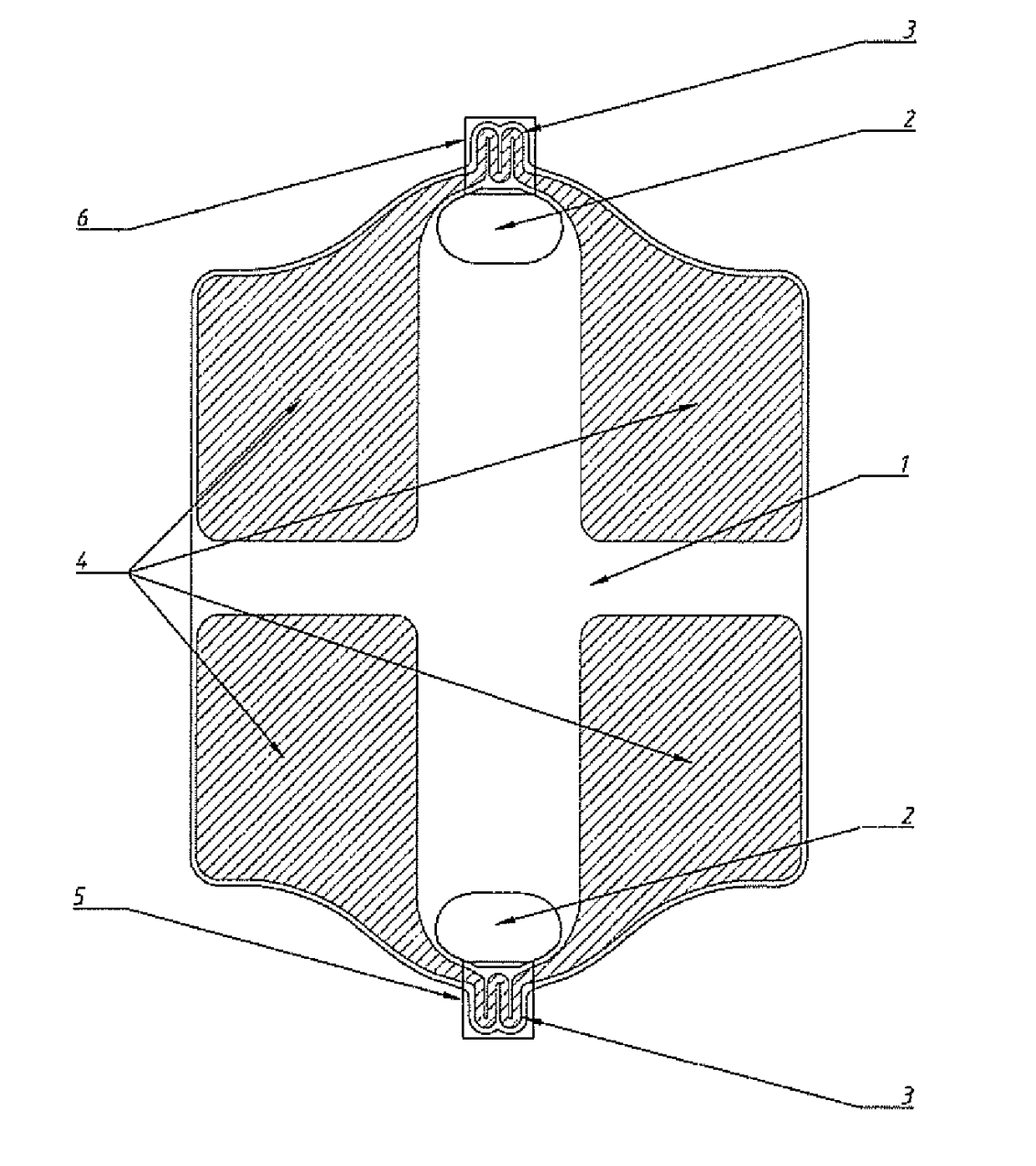
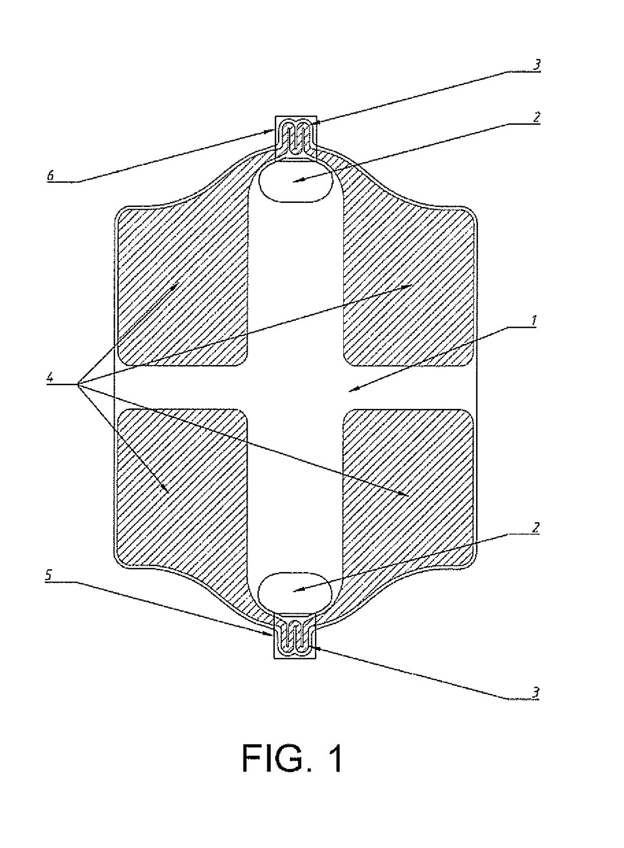
[0052]A main component of the planar thermocatalytic sensor is a microchip produced according to thin-film techniques (FIG. 1), said microchip being composed of a thin porous substrate (1) made of an anodic aluminium oxide film having a thickness of 30 μm, onto which platinum thin-film (300-1000 nm thick) structured coatings (shown as shaded areas in FIG. 1) are applied by vacuum deposition, i.e., two measuring microheaters (3) in the form of a meander, current lead wires to the microheaters, and contact pads (4).

[0053]In turn, main components of the microchip are the two identical measuring microheaters (3) any one of which may function as the measuring microheater of either a working (5) or a reference (6) sensitive elements, depending on which of them has been coated with a catalytically active layer.

[0054]During experiments performed, a high reproducibility of the identical configuration sensitive elements and of resistances of the measuring microheaters produced by a collective...


PUM

PropertyMeasurementUnit
thicknessaaaaaaaaaa
thicknessaaaaaaaaaa
pore diameteraaaaaaaaaa

Abstract

The invention relates to gas analysis and to combustible gas and vapour analyzers based on a thermocatalytic operating principle. The subject of the invention is a sensor the sensitive elements of which are manufactured by planar techniques that can be easily automated. The main distinguishing feature is that a working sensitive element and a reference sensitive element are colocated in a single micron-sized structural component (a microchip) on a common substrate made of porous anodic aluminium oxide. The design of the sensitive elements provides for film-wise heat transfer from heated parts of the working and reference sensitive elements. Measuring microheaters which heat the working and reference sensitive elements up to working temperatures and provide for differentially measuring an output signal in a measuring bridge circuit are spaced apart at opposite sides of the anodic aluminium oxide substrate and are disposed on arms projecting beyond the common substrate configuration. The sensitive elements are disposed in a reaction chamber having restricted diffusion access via a calibrated orifice, and the diameter of regular pores in the microchip substrate is increased to sizes that provide for a predominantly molecular diffusion mode in the pores (100 nm or more).

Description

TECHNICAL FIELD OF THE INVENTION[0001]The present invention relates to devices for gas analysis of combustible gases and vapours based of thermocatalytic principle, more particular to sensors of such devices.[0002]In literature there are several names being synonyms of the term “thermocatalytic sensor” such as “thermocatalytic detector,”“thermocatalytic primary transducer,”“thermocatalytic gas-measuring head” [Karpov E. F., Basovsky B. I., Control of ventilation and outgassing in coal mines. Handbook. Moscow, ‘Nedra’ Publisher, 1994]. All these terms give an accurate representation of functions performed by the devices and may include only sensitive elements placed inside an explosion-proof casing and protected against dust and turbulent flows of a gas-air mixture to be analyzed, or may additionally include partially or entirely a circuitry of the sensor device.[0003]In the present invention, implied under the term “thermocatalytic sensor” is the most common sensor design including ...

Claims


Application Information

Patent Timeline
Patent Type & Authority Applications(United States)
IPC IPC(8): G01N25/38G01N25/32
CPCG01N25/385G01N25/32G01N27/128G01N27/14
Inventor KARPOV, EVGENY EVGENIEVICHKARELIN, ALEXEY PAVLOVICHSUCHKOV, ALEXEY ANATOLIEVICHROSLYAKOV, ILYA VLADIMIROVICHKOLESNIK, IRINA VALERIEVNANAPOLSKII, KIRILL SERGEEVICH
Owner ROSNEFT OIL CO
Learn More