Separation membrane for olefin separation and olefin separation method using the same
- Summary
- Abstract
- Description
- Claims
- Application Information
AI Technical Summary
Benefits of technology
Problems solved by technology
Method used
Image

Examples
example 1
on of Composite Membrane for Olefin Separation 1
[0043]1.6 wt % sulfonated polysulfone solution (sulfonated polysulfone (Udel 6100): 1.5 g, water: 95.5 mL, acetic acid: 2.9 mL) was prepared, which was stirred for 12 hours. Chitosan (Sigma-Aldrich) was added thereto at the concentration of 0˜100 weight % by the total weight of the finally prepared separation membrane. The mixture was stirred again, followed by filtering to eliminate impurities. At this time, the finally prepared separation membrane indicates the separation membrane containing sulfonated polysulfone, chitosan, and transition metal which would be explained hereinafter.
[0044]The mixed solution excluding impurities above was casted on a polysulfone support, the porous support, leading to the formation of a regular membrane at room temperature. 5 hours later, the composite membrane (separation membrane+polysulfone, the porous support) was neutralized by impregnation in 500 mL of 1 M NaOH aqueous solution for 12 hours, and ...
example 2
on of Composite Membrane for Olefin Separation 2
[0047]A composite membrane for olefin separation was prepared in the same manner as described in except that 5 M copper chloride aqueous solution was used instead of 3 M silver nitrate (AgNO3) aqueous solution, polyethyleneimine (Sigma-Aldrich) was used instead of chitosan, and sulfonated polyetherether ketone (BASF, PEEK) was used instead of sulfonated polysulfone.
[0048]As a control, a composite membrane was prepared without adding polyethyleneimine or sulfonated polyetherether ketone, and the performance of the composite membrane was evaluated.
experimental example 1
on Performance of Composite Membrane for Olefin Separation 1
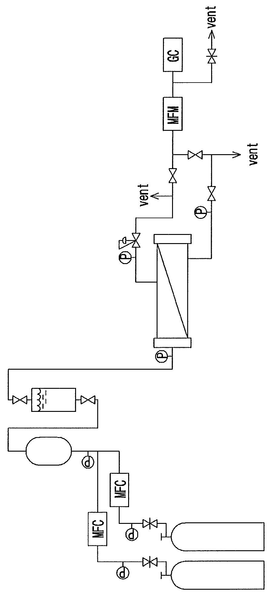
[0049]To evaluate the separation performance of the composite membrane for olefin separation prepared in the present invention, permeation equipment was equipped as shown in FIG. 1.
[0050]In the schematic diagram of permeation equipment of FIG. 1, the two bombes in the right bottom supply olefin gas and paraffin gas independently, and the humidifier connected to the two bombes is a device to supply humidity to the mixed gas of olefin and paraffin. The Membrane test cell connected to the humidifier is equipped with the composite membrane for olefin separation prepared in Examples 1 and 2, which is to measure the olefin permeability and selectivity. At this time, the permeability is expressed in units of GPU by calculating the permeation amount of the separation membrane from the area of the separation membrane, the permeation time, and the permeation pressure. The selectivity is calculated by the ratio of the permeability of ...
PUM
| Property | Measurement | Unit |
|---|---|---|
| Percent by mass | aaaaa | aaaaa |
| Percent by mass | aaaaa | aaaaa |
| Percent by mass | aaaaa | aaaaa |
Abstract
Description
Claims
Application Information
 - Generate Ideas
- Intellectual Property
- Life Sciences
- Materials
- Tech Scout
- Unparalleled Data Quality
- Higher Quality Content
- 60% Fewer Hallucinations
Browse by: Latest US Patents, China's latest patents, Technical Efficacy Thesaurus, Application Domain, Technology Topic, Popular Technical Reports.
© 2025 PatSnap. All rights reserved.Legal|Privacy policy|Modern Slavery Act Transparency Statement|Sitemap|About US| Contact US: help@patsnap.com