Method for Purifying Fluorine Compound Gas

a technology of fluorine compound gas and purification method, which is applied in the direction of lithium halide, dispersed particle separation, separation process, etc., can solve the problems of deterioration of product yield, increasing the difficulty of processing year by year, and the method described in the patent document 1 cannot be applied, so as to achieve the effect of simple structur

Active Publication Date: 2019-02-14
CENT GLASS CO LTD
View PDF7 Cites 8 Cited by
  • Summary
  • Abstract
  • Description
  • Claims
  • Application Information

AI Technical Summary

Benefits of technology

[0045]According to the present invention, metal components can be easily removed from a fluorine compound gas which contains the metal components as impurities by a device having a simple structure, and it is possible to provide a gas which can be used for use in etching and the like, corresponding to miniaturization in a semiconductor field.

Problems solved by technology

In the manufacture of a semiconductor device, due to the improvement of miniaturization and high integration technology, technical difficulty in processing is becoming higher year by year.
In such a situation, there is possibility that an impurity contained in a material of the semiconductor device becomes a factor causing a problem of the deterioration of yield of products in the manufacturing step for the semiconductor device.
However, in case where the differences in boiling point and melting point between a fluorine compound gas that will be purified and an impurity contained therein are small, the method described in the patent document 1 cannot be applied.
However, the sublimation of the metal impurity is extremely high, and moreover, the amount of the metal impurity contained in the fluorine compound gas as an impurity is small, and therefore there is a problem that the removal of the metal impurity by the cryogenic purification method is difficult.
In addition, when the cryogenic purification method is used, although its equipment is complicated and large, it is possible to install the equipment in a manufacturing factory for the fluorine compound gas.
However, when a small amount of the gas is treated, it is difficult to install the equipment and is therefore unsuitable.
However, the method has almost no effect on impurities other than hydrogen fluoride.

Method used


Image

  • Method for Purifying Fluorine Compound Gas

Examples


example

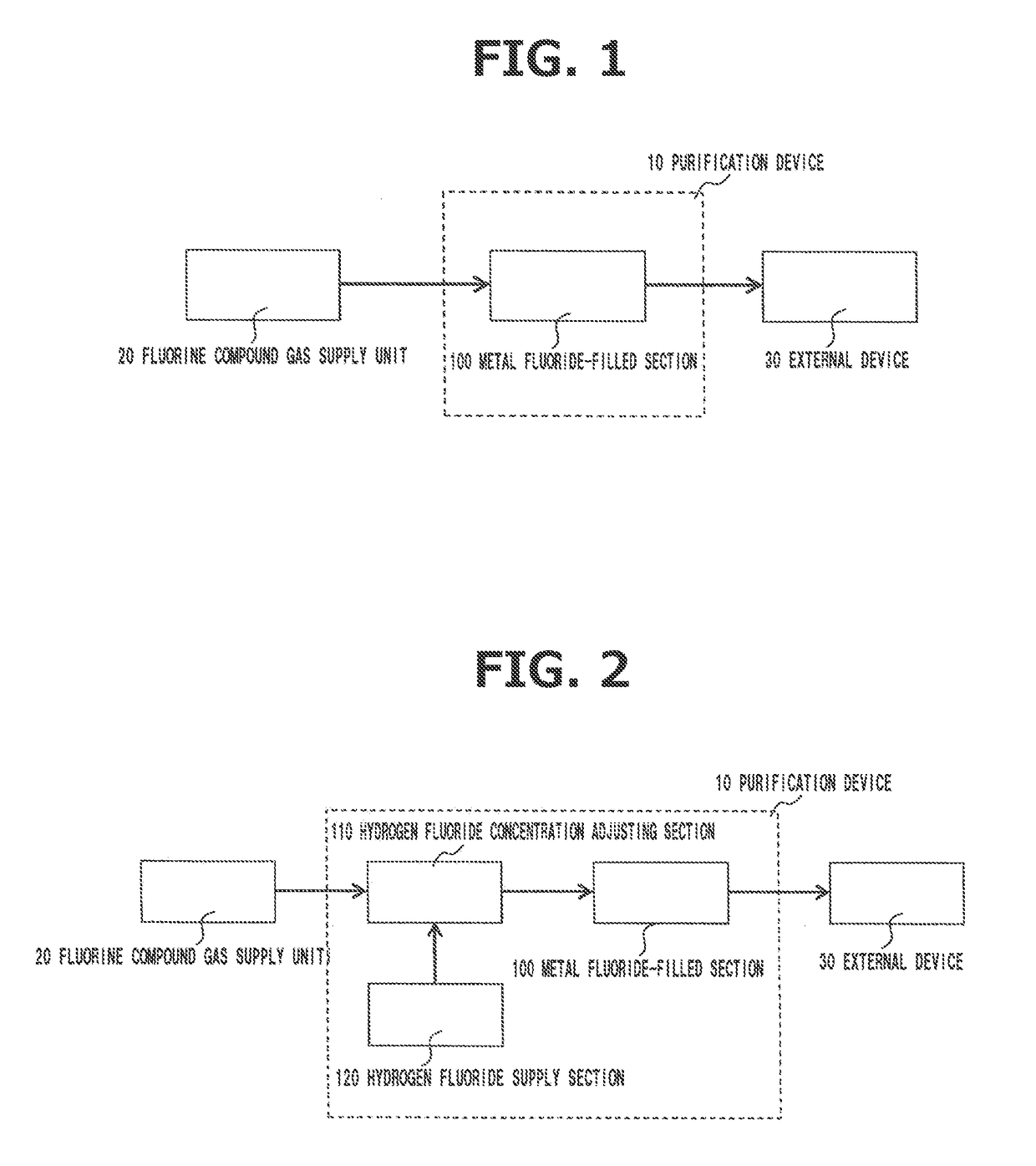
[0070]According to the system diagram shown in FIG. 2, cylinders filled with respective CIF, CIF3, IF7, BrF5, NF3 and WF6 (purity is 99 volume % or greater to 99.99 volume % or less) were used as the fluorine compound gas supply unit 20, and a cylinder filled with HF (HF purity: 99.99 volume %) was connected to the hydrogen fluoride supply section 120. In addition, although not shown in FIG. 2, as a flow amount control device, a mass flow controller (made by HORIBA STEC, Co., Ltd.) was provided on the downstream side of each of the cylinders, and by using them, the supply amount of each of the gases was controlled. In addition, as the metal fluoride-filled section 100, one was used in which a Ni-pipe having a diameter of 1 inch (25.4 mm)×200 mm which was filled with 100 g of NaF-pellet (made by MORITA CHEMICAL INDUSTRIES CO., LTD.). Further, the metal fluoride-filled section 100 was heated or cooled to room temperature or a predetermined temperature, and then was used. After that, t...


PUM

PropertyMeasurementUnit
boiling pointaaaaaaaaaa
temperatureaaaaaaaaaa

Abstract

Disclosed is a purification method for removing a metal component from a fluorine compound gas containing hydrogen fluoride and a metal component. This method includes a removing step for removing the hydrogen fluoride and the metal component therefrom by bringing the fluorine compound gas into contact with a solid metal fluoride to adsorb the hydrogen fluoride and the metal component on the metal fluoride. It is preferable for the fluorine compound gas to contain at least one kind selected from the group consisting of CIF, CIF3, IF5, IF7, BrF3, BrF5, NF3, WF6, SiF4, CF4, SF6 and BF3. It is also preferable for the metal fluoride to be an alkali metal fluoride or an alkali earth metal fluoride. Surprisingly, the presence of hydrogen fluoride in a fluorine compound gas makes it possible to remove a metal component therefrom as an impurity as a result of adsorption thereof by a metal fluoride.

Description

TECHNICAL FIELD[0001]The present invention relates to a fluorine compound gas purification method for purifying a fluorine compound gas by removing a metal component from a fluorine compound gas that contains a metal component as an impurity.BACKGROUND OF THE INVENTION[0002]A fluorine compound gas has been widely used in etching of substrate and cleaning gas in thin film formation such as CVD (Chemical Vapor Deposition), in manufacturing steps for semiconductor devices, MEMS (Micro Electro Mechanical Systems) devices, TFT (Thin Film Transistor) panels for liquid crystal and solar batteries, or used in fluorinating agents for fluorochemical product synthesis.[0003]In the manufacture of a semiconductor device, due to the improvement of miniaturization and high integration technology, technical difficulty in processing is becoming higher year by year. In such a situation, there is possibility that an impurity contained in a material of the semiconductor device becomes a factor causing ...

Claims


Application Information

Patent Timeline
Patent Type & Authority Applications(United States)
IPC IPC(8): B01D53/04
CPCB01D53/0423B01D2253/112B01D2256/26B01D2257/2047B01D2257/60C01B7/24C01D3/02C01D15/04Y02C20/30B01D53/04C01B21/083C01G41/04
Inventor YAO, AKIFUMIOOYA, KOHEITAKEDA, YUTAETO, JUN
Owner CENT GLASS CO LTD
Why Eureka
Try Eureka