Security element formed from at least two materials present in partially or fully overlapping areas, articles carrying the security element, and authentication methods

a technology of security elements and materials, applied in the field of security elements formed from at least two materials present in partially or fully overlapping areas, articles carrying the security element, and authentication methods, can solve the problems of loss of properties, limited choice of fluorescent products that can be incorporated into the ink formulation for these technologies, and additional limitations on the choice of fluorescent products. fluorescent products, and achieve the effect of strong authentication and stronger authentication of visible or invisible dots

Active Publication Date: 2019-05-02
SICPA HLDG SA
View PDF0 Cites 5 Cited by
  • Summary
  • Abstract
  • Description
  • Claims
  • Application Information

AI Technical Summary

Benefits of technology

[0021]In certain embodiments, the present invention further aims at providing a stronger authentication of visible or invisible Dot-Matrix codes, wherein a printed code is securely linked to a printing substrate, such as a label or package, and which can be authenticated without requiring expensive or complex reading device.
[0022]In certain embodiments, the present invent

Problems solved by technology

The use of such security elements is becoming more and more widespread in view of increasing numbers of forged and bogus products, as the security element poses a difficulty to any counterfeiter in the reproduction of bogus products.
The choice of suitable fluorescent products that can be incorporated in the ink formulation for these technologies is limited due to the small size of the printer head nozzles.
CH or DoD printers have tiny nozzles which would be clogged by the phosphor pigments and crushing the pigment particles to smaller sizes lead to a loss of their properties.
When codes are printed such that they are not visible to unaided eye, there are even additional limitations on the choice of fluorescent products and more stringent requirements on ink formulation.
An additional problem with actual methods used for serialization of product with printed secure Dot-matrix codes on pre-printed labels is that the link between the label and the code is not secured.
In other words, non-serialized pre-printed labels can be stolen by bad people who could potentially print their own serialization codes for counterfeiting products.
Further, such conventional security elements rely on the use of one species only for forming the security element.
With a standard imaging sensor, performing multi (or hyper) spectral imaging, e.g. in the NIR (near infrared range) range, would require techniques such as: (1) custom Bayer-like filters (involving expensive developments) (2) Fabry-Perot configurations (currently bulky and fairly expensive), (3) complex came

Method used


Image

  • Security element formed from at least two materials present in partially or fully overlapping areas, articles carrying the security element, and authentication methods
  • Security element formed from at least two materials present in partially or fully overlapping areas, articles carrying the security element, and authentication methods
  • Security element formed from at least two materials present in partially or fully overlapping areas, articles carrying the security element, and authentication methods

Examples


example 1

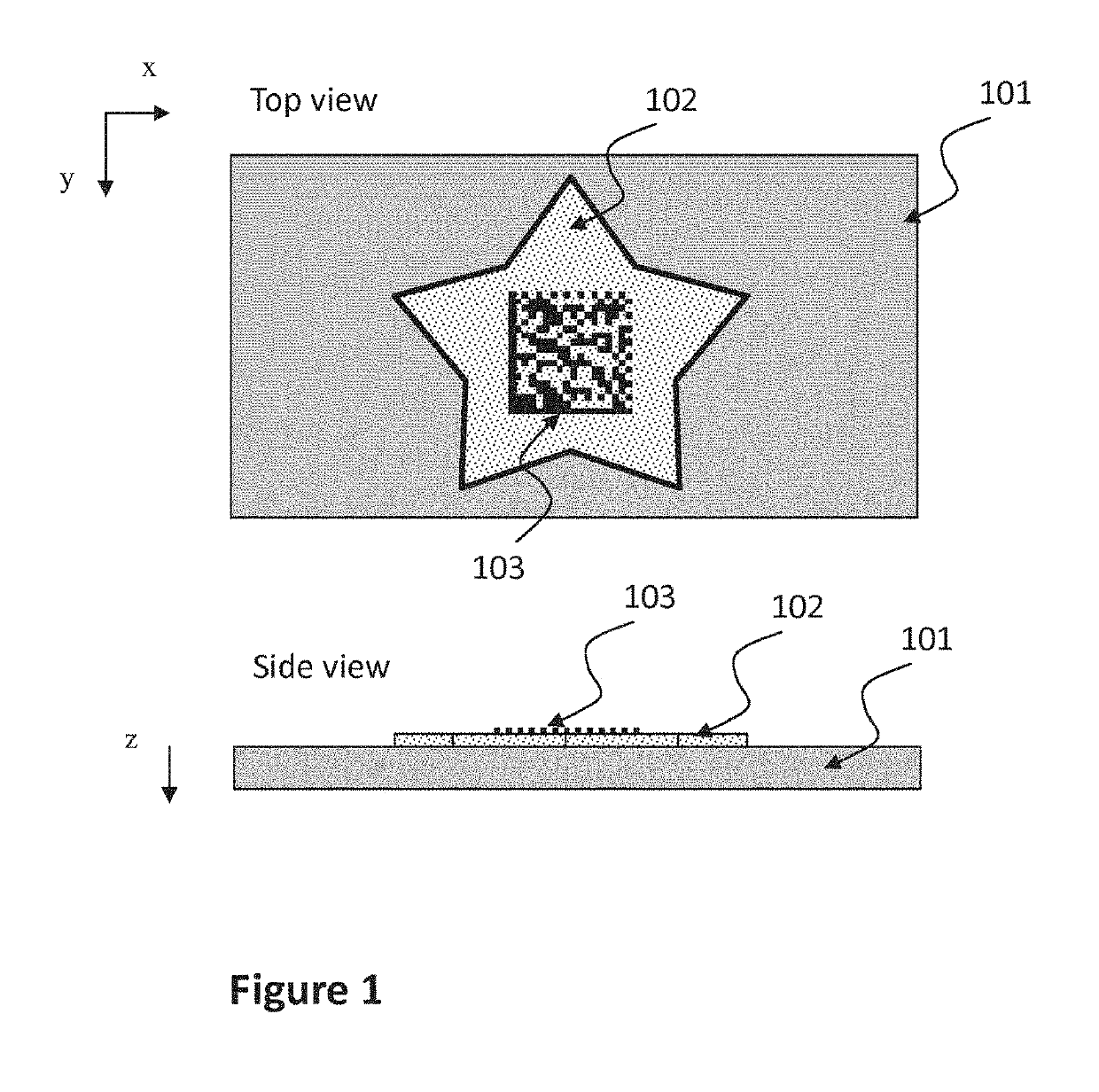
[0241]In order to demonstrate the invention, several marks composed of a phosphorescent print made from INK1 with digitally printed codes or logos on top made from INK2 were produced (see Table 1 below)

[0242]Preparation of long afterglow background ink (INK1):

[0243]The phosphorescent pigments were incorporated in the formulation of silk screen inks based on the following blank composition:

[0244]31.5 wt.-% Tripropyleneglycol diacrylate monomer, 17.9 wt.-% trimethylolpropane triacrylate, 19.0 wt.-% FBECRYL™ 2959, 11.6 wt.-% EBECRYL™ 80, 2.1 wt.-% TEGO® Airex 900, 1.0 wt.-% GENORAD™ 20, 9.5 wt.-% Calcium carbonate, 2.1 wt.-% Benzil dimethyl ketal and 5.3 wt.-% IRGACURE™ 1173. While this system is preferably used for the present invention, also other systems can be employed as long as it is ensured that there is no or very little spectroscopic or chemical interferences of the blank with the phosphorescence of the phosphorescent pigments that will be added to form MAT1 or INK1, INK1 can ...

example 2

[0272]In the following example 2, two different formulations of INK1 were tested based on the following blank properties in order to determine the effect of ink compositions on the observed cascade effect:

[0273]1) INK1 with solvent-based blank formulation (FORMULATION blank A) Where the dry inks layer is thin and hence pigments are concentrated and much of them are close to the top surface

[0274]2) INK1 with UV-curable resin blank formulation (FORMULATION blank B) where dry ink layer is significantly thicker, the pigments are homogeneously distributed along the thickness (z axe) of the print layer, and consequently, the pigment concentration at the surface of the print is reduced as compared to the solvent based ink

[0275]Both of these inks blanks are used for silk-screen inks and their espective formulations are described in details below, For the example described here, two examples of INK1 using the two different blanks were formulated by adding 15%-weight of Lumilux® green SN-F2Y ...


PUM


Abstract

Security element comprising a first material MAT1 and a second material MAT2 formed in or on a substrate, in such a manner that areas occupied by MAT1 and MAT2 overlap partially or fully,
the first material MAT1 comprising a phosphorescent pigment (donor), the second material MAT2 comprising a fluorescent dye or pigment (acceptor),
wherein the phosphorescent pigment present in MAT1 is capable of emitting phosphorescence radiation in at least one first phosphorescence emission wavelength range λ1e upon excitation by electromagnetic radiation falling within a phosphorescence excitation wavelength range λ1a, and
the fluorescent dye or pigment present in MAT2 is capable of emitting fluorescence radiation in at least one second fluorescence emission wavelength range λ2e upon excitation by electromagnetic radiation falling within an fluorescence excitation wavelength range λ2a of the fluorescent dye or pigment, and
said first phosphorescence emission wavelength range λ1e of the phosphorescent pigment present in MAT1 overlaps with the excitation wavelength range λ2a of the fluorescent dye or pigment present in MAT2, so that after irradiation of the security element with electromagnetic radiation within the phosphorescence excitation wavelength range λ1a the emission of fluorescence radiation in the emission wavelength range λ2e is observable.

Description

BACKGROUND OF THE INVENTION[0001]Security elements are often used to indicate the authenticity and genuineness of various items, including banknotes, member cards, concert tickets, different kinds of commercial goods of value such as perfumes, fashion items or replacement parts for cars and planes, just to mention a few. The use of such security elements is becoming more and more widespread in view of increasing numbers of forged and bogus products, as the security element poses a difficulty to any counterfeiter in the reproduction of bogus products.[0002]Security elements that are based on fluorescence phenomenon are widely used. Fluorescence is observed if a fluorescent material, typically a dye or pigment, is exposed to excitation radiation. It follows a decay of the excited material, causing emission as a wavelength different from the excitation wavelength. The response of the material (i.e. the intensity and / or color of the observed emission in response to the excitation) is in...

Claims


Application Information

Patent Timeline
IPC IPC(8): B42D25/378B42D25/382B42D25/387B42D25/405G07D7/00G07D7/1205G01N21/64G06K19/06G06K7/14C09D11/50C09D11/037C09D11/54B41M3/14
CPCB42D25/378B42D25/382B42D25/387B42D25/405G07D7/003G07D7/1205G01N21/6456G06K19/06103G06K19/06028G06K19/06037G06K7/1413G06K7/1417G06K7/1443C09D11/50C09D11/037C09D11/54B41M3/144G07D2207/00G07D7/12C09D11/033C09D11/101C09D11/106C09D11/30
Inventor DORIER, JEAN-LUCMILOS-SCHOUWINK, MIARAEMY, XAVIER CEDRIC
Owner SICPA HLDG SA
Why Eureka
Try Eureka