Honeycomb structure

a honeycomb and structure technology, applied in the field of honeycomb structure, can solve the problems of inability to solve, inability to inhibit anything, and inability to so as to improve the thermal shock resistance of the whole honeycomb structure, effectively inhibit crack generation, and improve the effect of thermal shock resistan

Active Publication Date: 2019-05-30
NGK INSULATORS LTD
View PDF0 Cites 5 Cited by
  • Summary
  • Abstract
  • Description
  • Claims
  • Application Information

AI Technical Summary

Benefits of technology

[0024]A honeycomb structure of the present invention has an excellent thermal shock resistance. That is, the honeycomb structure of the present invention is capable of effectively inhibiting generation of cracks due to a thermal shock, as compared with a conventional honeycomb structure having about the same degree of porosity. In particular, when a porosity of the partition walls is adjusted to 10 to 40% and a porosity B of the partition wall in an intersecting portion connecting two or more wall portions is appropriately decreased, the thermal shock resistance of the whole honeycomb structure can improve. Specifically, when the porosity of the partition walls is 40% or less, for example, a catalyst for exhaust gas purification is hard to penetrate into pores formed in the partition walls. Consequently, in a case where the conventional honeycomb structure is used as a catalyst carrier in strict thermal conditions, for example, directly under a car engine, cracks are generated in the wall portions of the partition walls in an early period, because a thickness of the wall portion of each partition wall is smaller than that of the intersecting portion of the partition wall. Furthermore, there are concerns that the cracks generated in the wall portions of the partition walls easily develop into larger cracks, and defects of the honeycomb structure become worse. Here, for example, when the thickness of the wall portion of the partition wall is increased, the thermal shock resistance of the honeycomb structure can improve, but when the thickness of the partition walls is increased, a pressure loss rise of the honeycomb structure might be caused. In the honeycomb structure of the present invention, a porosity A of the partition walls in the wall portions in which the cracks are more easily generated is adjusted to be relatively low, and the above-mentioned A / B is adjusted to 0.5 to 0.95, so that it is possible to effectively inhibit the generation of the cracks in both of the wall portion and the intersecting portion of the partition wall. Additionally, in a cross section of the honeycomb structure of the present invention which is perpendicular to an extending direction of the cells, it is not necessary to partially change the thickness of the partition walls or to partially change a cell shape, and hence secondary problem such as the pressure loss rise is hard to occur.

Problems solved by technology

However, in the honeycomb structure described in Patent Document 1, a configuration of the partition walls in the central portion of the cross section is not changed from that of a conventional honeycomb structure, and hence there has been the problem that the improvement cannot be a countermeasure to inhibit generation of cracks due to a thermal shock load.
However, when the central portion is only focused, there has been the problem that anything is not resolved in that partition wall in a partitioning wall portion between two cells becomes a starting point of generation of cracks in a case where the cracks are generated by the thermal shock load.
In this honeycomb structure, there has been the problem that anything is not solved in that the partition wall in a partitioning wall portion between two cells become a starting point of generation of cracks, though the intersecting portion of the partition walls is strengthened.

Method used


Image

  • Honeycomb structure
  • Honeycomb structure
  • Honeycomb structure

Examples


first embodiment

(1) Honeycomb Structure (First Embodiment)

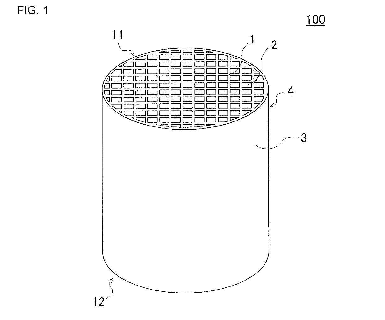
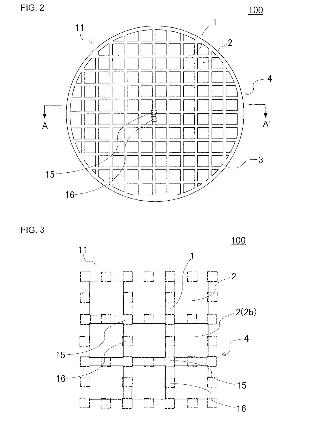
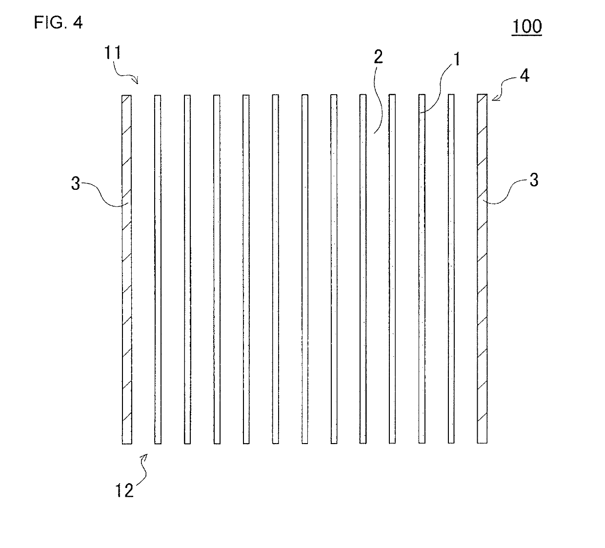
[0034]As shown in FIG. 1 to FIG. 4, a first embodiment of a honeycomb structure of the present invention is a honeycomb structure 100 including a honeycomb structure body 4 having porous partition walls 1. Here, FIG. 1 is a perspective view schematically showing the first embodiment of the honeycomb structure of the present invention as seen from the side of a first end face. FIG. 2 is a plan view schematically showing the first end face of the honeycomb structure shown in FIG. 1. FIG. 3 is an enlarged plan view in which a part of the first end face of the honeycomb structure shown in FIG. 2 is enlarged. FIG. 4 is a cross-sectional view schematically showing a cross section taken along the A-A′ line of FIG. 2.

[0035]The partition walls 1 of the honeycomb structure body 4 are arranged to surround a plurality of cells 2 which extend from a first end face 11 to a second end face 12 and become through channels for a fluid. That is, the plurality ...

example 1

[0074]To 100 parts by mass of cordierite forming raw material, 0.5 parts by mass of a pore former, 33 parts by mass of a dispersing medium and 5.6 parts by mass of an organic binder were added, mixed and kneaded to prepare a kneaded material. As the cordierite forming raw material, alumina, aluminum hydroxide, kaolin, talc and silica were used. Water was used as the dispersing medium, a water absorbable polymer having an average particle diameter of 10 to 50 μm was used as the pore former, methylcellulose was used as the organic binder, and dextrin was used as a dispersing agent.

[0075]Next, the kneaded material was extruded by using a predetermined die, to obtain a honeycomb formed body in which a cell shape was quadrangular and an overall shape was a round pillar shape. Additionally, during the extrusion, there was used an extruding die in which slits corresponding to a cross-sectional shape of the honeycomb formed body were formed, and in the extrusion, an extrusion speed was rais...

examples 2 to 20

[0083]A cell structure, a cross-sectional shape and a porosity A and a porosity B of partition walls were changed as shown in Table 1 and Table 2, to prepare honeycomb structures of Examples 2 to 20. As to Examples 5, 6, 13 and 14, a cell shape was a hexagon. Furthermore, as to Examples 7 and 8, a cross-sectional shape of the honeycomb structure was an ellipse.

[0084]As to Examples 19 and 20, silicon carbide (SiC) was used as a material to prepare the honeycomb structure. The honeycomb structure of each of Examples 19 and 20 was a honeycomb structure of a segmented structure.

[0085]During preparation of the honeycomb structures of Examples 2 to 20, an extrusion pressure during extrusion was adjusted, and values of a porosity A and a porosity B of partition walls were adjusted.

[0086]As to the honeycomb structures of Examples 1 to 20, evaluations on “thermal shock resistance (robustness)” were performed by the following method. Table 3 shows the results.

[0087](Thermal Shock Resistance (...


PUM

PropertyMeasurementUnit
porosityaaaaaaaaaa
porosityaaaaaaaaaa
thicknessaaaaaaaaaa

Abstract

A honeycomb structure includes a honeycomb structure body having porous partition walls, wherein a value of a porosity of the partition wall in a partitioning wall portion between the two cells is defined as a porosity A, a value of a porosity of the partition wall in an intersecting portion that is a region connecting two or more wall portions is defined as a porosity B, a value of A/B obtained by dividing the porosity A by the porosity B is from 0.5 to 0.95, and the porosity A is from 10 to 40%.

Description

[0001]The present application is an applications based on JP-2017-225577 filed on Nov. 24, 2017 and JP2018-196101 filed on Oct. 17, 2018 with Japan Patent Office, the entire contents of which are incorporated herein by reference.BACKGROUND OF THE INVENTIONField of the Invention[0002]The present invention relates to a honeycomb structure, and more particularly, it relates to a honeycomb structure having an excellent thermal shock resistance.Description of the Related Art[0003]In recent years, consciousness to environmental problems has increased in the whole society, and in a technical field in which fuel is burnt to generate power, various technologies have been developed to remove toxic components such as nitrogen oxides from an exhaust gas generated during the burning of the fuel. For example, various technologies have been developed to remove the toxic components, such as nitrogen oxides, from the exhaust gas emitted from a car engine. During such removal of the toxic components ...

Claims


Application Information

Patent Timeline
Patent Type & Authority Applications(United States)
IPC IPC(8): B01J35/04B01D53/94F01N3/28
CPCB01J35/04B01D53/9454F01N3/2828F01N2330/06F01N2330/34C04B38/0006C04B2111/00793C04B2111/0081F01N2330/60C04B35/00C04B38/0074
Inventor KATO, YASUSHIKONDO, TAKAHIROMATSUYA, JUNKI
Owner NGK INSULATORS LTD
Why Eureka
Try Eureka