Fast two-photon imaging by diffracted swept-laser excitation

a technology of diffracted laser excitation and two-photon fluorescence, which is applied in the field of high-speed nonlinear imaging systems and methods for two-photon fluorescence and fluorescence lifetime imaging, can solve the problems of limiting frame rate, reducing nonlinear vs. linear process efficiency, and challenging high-speed achieving. achieve the effect of fast non-linear imaging speeds

Active Publication Date: 2019-07-25
UNIV ZU LUBECK +1
View PDF0 Cites 8 Cited by
  • Summary
  • Abstract
  • Description
  • Claims
  • Application Information

AI Technical Summary

Benefits of technology

[0021]The imaging speed of the present multi-photon system is given by the speed of the slow-axis scanning device. Here, resonant galvanometric mirrors can be used to achieve frame-rates of 1-40 kHz. This means, that the slow-axis (scanner) can have speeds of the fast-axis of today's state-of-art multi-photon systems, resulting in orders of magnitud

Problems solved by technology

However, achieving high speed is challenged by lower efficiency of nonlinear vs. linear processes requiring illumination with a high-intensity tightly-focused beam that is scanned over sample area.
The scanning is typically done with mechanical scanners, the speed of which limits the frame rate.
Acousto-optic scanners provide an intermediate solution; however, the frame rate is limited by the acoustic velocity leading to a trade-off between resolution and speed.
Such mechanically scanning mirrors are inertia-limited and too slow for 2-D frame-rates in the biologically important kHz range.
However, these approaches have added complexity, require dispersion management and lack high timing resolution.
The finite latenc

Method used


Image

  • Fast two-photon imaging by diffracted swept-laser excitation
  • Fast two-photon imaging by diffracted swept-laser excitation

Examples


example 1

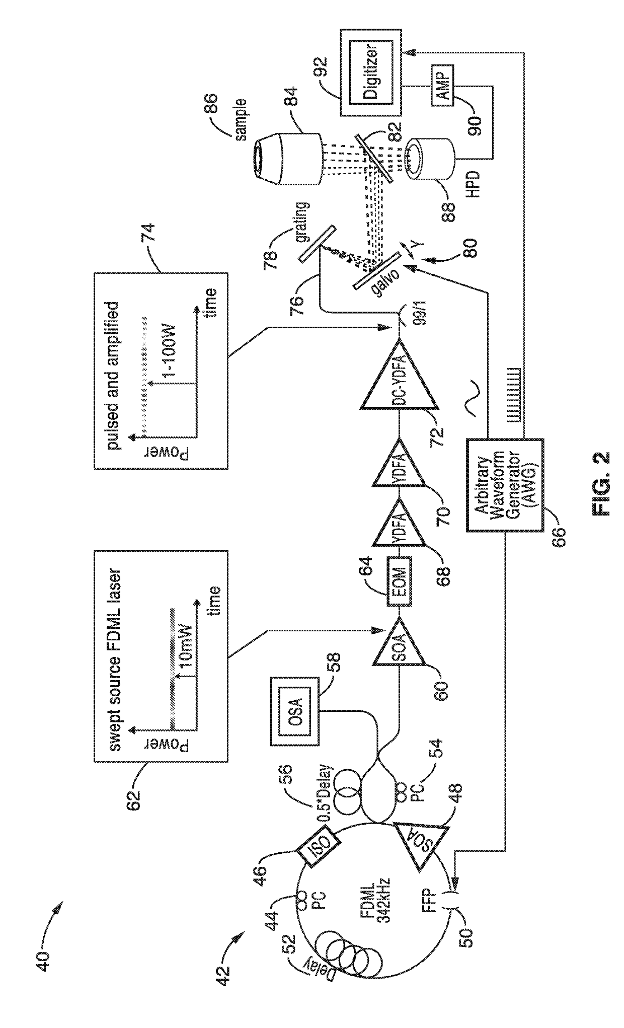
[0056]In order to demonstrate the operational principles of the apparatus and the capture and identification methods, a testing apparatus embodiment was fabricated with a structure and processing steps shown generally in FIG. 2 and tested.

[0057]The setup of the Spectro-temporal Lifetime Imaging by digitally sculpted excitation (SLIDE) system embodiment 40 shown if FIG. 2 has a light source 42 with a wavelength swept FDML laser at 1060 nm (±6 nm) and 342 kHz sweep repetition rate. The light source 42 in this embodiment has a PC: Polarization Controller 44, an ISO: Isolator 46, a SOA: semiconductor optical amplifier 48 a FFP: Fiber Fabry-Pérot Filter 50, and a delay 52. The light source output 62 also has a PC: Polarization Controller 54, a delay 56 and an OSA: optical spectrum analyzer 60. The wavelength sweep is accomplished by the fibre Fabry-Pérot-Filter (Lambdaquest) 50 driven at 171 kHz. The FDML output is two-times buffered to 342 kHz sweep rate. After the buffer stage, a boost...

example 2

[0067]For cell classification and detection of rare cells, such as circulating tumour and fetal cells, it is important to measure a high number of cells quickly, accurately and as non-invasively as possible. Two-photon microscopy has high three dimensional resolution, can operate in blood flow and offers deeper penetration than one-photon techniques through the use of longer wavelengths. Two photon imaging in flow may also be used for non-invasive in vivo cancer cell detection through the skin barrier.

[0068]To further illustrate the capabilities of the system, Two-Photon Fluorescence Lifetime Imaging (2P-FLIM) based flow cytometry at an 88 MHz pixel rate was demonstrated. The particles were fluorescent beads used in blood flow determination studies with diameters in the range 2 μm to 15 μm, similar to typical cell sizes. The flow-rate was set to 0.2 m / s, limited by diffraction spot size and fluorescent lifetime.

[0069]In the flow cytometry recordings, the flow-rate was set by two fun...

example 3

[0072]To further demonstrate the capabilities of the system, high speed two photon fluorescent images and fluorescent lifetime images of pollen and algae cells were obtained and evaluated. Fluorescent imaging can be used for classifications of algae cells used in biofuels based on their lipid content. Euglena gracilis algae cells with rich lipid content were stained with Nile Red. The cell's chloroplasts provide endogenous autofluorescence and the difference in fluorescent lifetimes clearly highlight the different sub-cellular features. These images were unaveraged and acquired within 497 μs for both TPEF and 2P-FLIM images that were acquired simultaneously. The lifetimes were extracted by de-convolving with the instrument's response function.

[0073]For precise measurement, a deconvolution with the IRF was conducted in order to extract the fluorescent lifetimes. However, this was time consuming, so for faster processing and qualitative results a tail-fitting algorithm was used. In so...


PUM


Abstract

An apparatus and methods for high-speed non-linear spectrally encoded multi-photon imaging that are particularly suited for use in two photon fluorescence and fluorescence lifetime imaging. The system is capable of optical image compression and scale invariant digital zoom. A wavelength agile laser with digitally synthesized electro-optic modulation in a master oscillator-power amplifier configuration is combined with spectral encoding to eliminate the speed limitations of inertial scanning. The technique for fast two photon fluorescent imaging with simultaneous lifetime imaging independently detects the location, amplitude and lifetime of fluorescent emission by synthesizing a sequential excitation beam via digital electro-optic modulation of a quasi-CW swept source followed by time encoded detection. For fluorescent imaging, spectral and temporal mappings are employed separately, with quasi-CW spectral encoding used for pumping and time encoding for constructing the image at fluorescence wavelength.

Description

CROSS-REFERENCE TO RELATED APPLICATIONS[0001]This application claims priority to, and is a 35 U.S.C. § 111(a) continuation of, PCT international application number PCT / US2017 / 039705 filed on Jun. 28, 2017, incorporated herein by reference in its entirety, which claims priority to, and the benefit of, U.S. provisional patent application Ser. No. 62 / 355,571 filed on Jun. 28, 2016, incorporated herein by reference in its entirety. Priority is claimed to each of the foregoing applications.[0002]The above-referenced PCT international application was published as PCT International Publication No. WO 2018 / 005623 A1 on Jan. 4, 2018, which publication is incorporated herein by reference in its entirety.STATEMENT REGARDING FEDERALLY SPONSORED RESEARCH OR DEVELOPMENT[0003]This invention was made with Government support under Grant number GM107924, awarded by the National Institutes of Health. The Government has certain rights in the invention.INCORPORATION-BY-REFERENCE OF COMPUTER PROGRAM APPE...

Claims


Application Information

Patent Timeline
IPC IPC(8): G01N21/64H01S3/00H01S3/067G02B21/00
CPCG01N21/6402H01S3/0085H01S3/06758H01S3/0071G02B21/0084G02B21/0076G01N21/6408H01S3/1618G01N2201/06113G01N2201/0696G01N2201/1053A61B5/0071G01N21/00H01S3/06712H01S3/083H01S3/1305H01S5/146H01S5/50A61B5/0075
Inventor KARPF, SEBASTIANJALALI, BAHRAMHUBER, ROBERT
Owner UNIV ZU LUBECK
Why Eureka
Try Eureka