Photonic crystal comprising photo-responsive molecules and method of preparing the same
a photoresponsive and crystal technology, applied in the field of photonic crystals, can solve the problems of difficult structure modification, high cost, and difficulty in modifying the structure, and achieve the effect of not easy to use the self-assembly method to pattern a large area, and requiring several steps and entail high cos
- Summary
- Abstract
- Description
- Claims
- Application Information
AI Technical Summary
Benefits of technology
Problems solved by technology
Method used
Image
Examples
example
Example 1: Production of Photonic Crystal
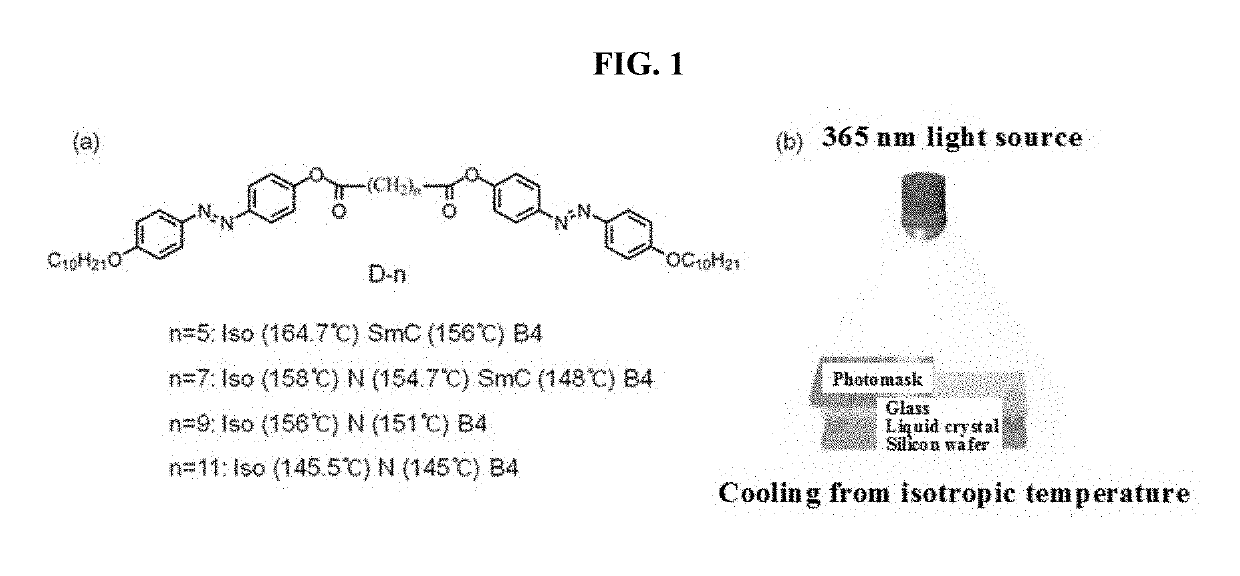
[0053]First, a sandwich cell using a silicon substrate (lower plate) and a glass substrate (upper plate) was produced. The reason for using a silicon substrate is to prevent undesired further scattering and reflection of incident white light so that the reflection color from the liquid crystal film can be seen clearly, and the reason for using a glass substrate is to transmit the light to the sample. Spacing between the substrates was maintained using a few micrometers (μm) of silica beads. A liquid crystal sample was injected into a cell using a capillary force at an isothermal temperature of about 170° C.
[0054]The liquid crystal sample used was divided into D-5, D-7, D-9 and D-11 corresponding to Chemical Formulae 2-1, 2-2, 2-3 and 2-4, respectively, depending on the number of alkyl groups in a central linking part.
TABLE 1Isotropic temperature, nematic phase and smecticphase temperatures of liquid samplesIsotropic temperatureNematic phaseSm...
example 2
ation of Chirality Using Photonic Crystal Film
[0061]It was found that circularly polarized light is reflected from a helical photonic crystal film. The chirality of the produced photonic crystal film can be identified using a quarter wave plate and a linear polarizer capable of retarding the phase of light by a quarter wavelength. In this case, since the helical structure is a racemic compound having a combination of levorotation and dextrorotation, left circularly polarized light and right circularly polarized light are reflected together. It can be seen from the right side of FIGS. 5A and 5B that two types of circularly polarized light are converted to mutually different types of linearly polarized light while passing through the wave plate. The linear polarized light thus converted is selectively transmitted by a linear polarizer present in the rightmost part. That is, as shown in FIGS. 5C, 5D and 5E, domains, which are clearly distinguishable as linearly polarized light is rotat...
PUM
| Property | Measurement | Unit |
|---|---|---|
| reflection wavelength | aaaaa | aaaaa |
| reflection wavelength | aaaaa | aaaaa |
| reflection wavelength | aaaaa | aaaaa |
Abstract
Description
Claims
Application Information
 - R&D
- Intellectual Property
- Life Sciences
- Materials
- Tech Scout
- Unparalleled Data Quality
- Higher Quality Content
- 60% Fewer Hallucinations
Browse by: Latest US Patents, China's latest patents, Technical Efficacy Thesaurus, Application Domain, Technology Topic, Popular Technical Reports.
© 2025 PatSnap. All rights reserved.Legal|Privacy policy|Modern Slavery Act Transparency Statement|Sitemap|About US| Contact US: help@patsnap.com


