Methods for forming aryl carbon-nitrogen bonds using light and photoreactors useful for conducting such reactions

a technology of carbon-nitrogen bonds and light, which is applied in the preparation of organic compounds/hydrides/coordination complexes, physical/chemical process catalysts, amino preparations from amines, etc., can solve the problems of inefficient photoreactors used in connection with such photoreactions, harsh reaction conditions, and precious metal catalysts

Active Publication Date: 2019-11-14
COLORADO STATE UNIVERSITY
View PDF0 Cites 5 Cited by
  • Summary
  • Abstract
  • Description
  • Claims
  • Application Information

AI Technical Summary

Benefits of technology

[0019]These and other aspects and iterations of t

Problems solved by technology

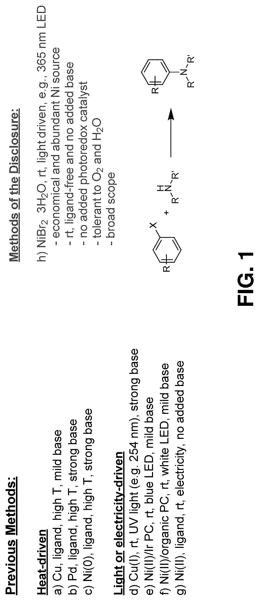
Transition metal complexes can elegantly orchestrate diverse assemblies of aminations, however they typically require harsh reaction conditions,

Method used


Image

  • Methods for forming aryl carbon-nitrogen bonds using light and photoreactors useful for conducting such reactions
  • Methods for forming aryl carbon-nitrogen bonds using light and photoreactors useful for conducting such reactions
  • Methods for forming aryl carbon-nitrogen bonds using light and photoreactors useful for conducting such reactions

Examples


example 1

-Coupling Via Direct Photoexcitation of Nickel-Amine Complexes

[0097]General Procedure A:

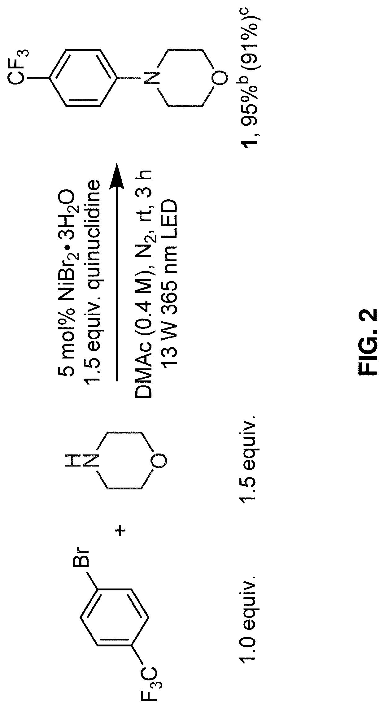
[0098]Under nitrogen atmosphere in a glovebox, a stir bar, an aryl halide (0.40 mmol, 1.0 equivalent), and 1 mL of DMAc solution containing dissolved NiBr2.3H2O (0.02 mmol, 0.05 equiv., 5.5 mg) was added to a 0.5 dram glass vial. The glass vial was then capped using a screw cap equipped with a PTFE / silicone septum and sealed with a strip of PARAFILM. The capped vial was then brought out of the glovebox and liquid amine (degassed, 1.40 mmol, 3.5 equiv.) was added via a HAMILTON syringe. Solid amines were weighed and added inside the glovebox. The capped glass vial containing the reaction mixture was then placed in a 3D-printed vial holder and subjected to 365 nm LED irradiation with fan cooling to maintain the vial at room temperature. After the time specified in the reaction schemes, the reaction mixture was washed with water, extracted with EtOAc or DCM and concentrated under vacuum. Purificatio...

example 2

ic Study

[0192]To further establish the utility of the C—N cross-coupling methodology of the disclosure, it was employed in multi-step syntheses (FIG. 12A and FIG. 12B). Recently, a visible light-driven aryl C—S cross-coupling methodology that proceeds under mild conditions to synthesize a wide range of aryl thioether products through white LED irradiation of a solution containing (hetero)aryl thiol, (hetero)aryl halide and Cs2CO3 in DMSO at room temperature in the absence of catalysts was reported.30 Using this method, aryl thioether 37 was synthesized at 56% yield which was subsequently subjected to the C—N cross-coupling conditions described herein, coupling it with 3-aminopyridine, to yield 38 in 88% yield (FIG. 12A). This example highlights two industrially important processes, namely aryl C—S and C—N cross-couplings that can be driven by light irradiation under mild conditions to reach molecular complexity.

[0193]The piperazine functionality is abundant across pharmaceutical pro...


PUM

PropertyMeasurementUnit
Temperatureaaaaaaaaaa
Fractionaaaaaaaaaa
Fractionaaaaaaaaaa

Abstract

The disclosure relates to a method for forming aryl carbon-nitrogen bonds and to photoreactors useful in these and other light-driven reactions. The method comprises contacting an aryl halide with an amine in the presence of a Ni salt catalyst solution and an optional base, thereby forming a reaction mixture; exposing the reaction mixture to light under reaction condition sufficient to produce the aryl carbon-nitrogen bonds. In certain embodiments, the amine may be present in a molar excess to the aryl halide. In certain embodiments, the Ni salt catalyst solution includes a Ni(II) salt and a polar solvent, wherein the Ni(II) salt is dissolved in the polar solvent. In certain embodiments, the reactions conditions include holding the reaction mixture at between about room temperature and about 80° C. for between about 1 hour and about 20 hours such that at least about 50% yield is obtained.

Description

CROSS-REFERENCE TO RELATED APPLICATIONS[0001]The present application incorporates in its entirety and claims the benefit under 35 U.S.C. § 119(e) of U.S. Provisional Application No. 62 / 668,515 filed May 8, 2018, the contents of which is hereby incorporated by reference in its entirety.GOVERNMENTAL RIGHTS[0002]This invention was made with government support under F32GM122392 and R35GM119702 awarded by the National Institutes of Health and DE-AR0000683 awarded by the Defense Advanced Research Projects Agency. The government has certain rights in the inventions disclosed.FIELD OF THE INVENTION[0003]The present disclosure relates to methods for forming aryl carbon-nitrogen bonds and to photoreactors useful for conducting these and other light-driven reactions.BACKGROUND OF THE INVENTION[0004]C—N cross-coupling is an important class of reactions with far-reaching impacts across chemistry, materials science, biology, and medicine. Transition metal complexes can elegantly orchestrate diver...

Claims


Application Information

Patent Timeline
IPC IPC(8): C07D295/073C07D211/06C07D211/62C07D211/46C07C209/68C07D307/52C07D213/74C07D213/38C07D239/26C07D235/26B01J19/12B01J27/08B01J35/00
CPCC07D295/073B01J35/004C07C2601/14C07D235/26C07D213/38B01J2219/1203C07D213/74B01J19/123B01J27/08C07D239/26B01J2219/0892C07D211/06C07D211/46C07C209/68B01J2219/0877C07D211/62C07D307/52C07C209/60B01J19/127B01J27/128B01J31/0237B01J31/0247B01J31/181B01J31/0271B01J31/0204B01J2231/4283B01J2531/847C07C211/45C07C211/48C07C211/56C07D207/04
Inventor MIYAKE, GARRETLIM, CHERN-HOOIKUDISCH, MAXLIU, BIN
Owner COLORADO STATE UNIVERSITY
Why Eureka
Try Eureka