
Photomask blank, photomask, and photomask manufacturing method

Active Publication Date: 2020-01-09
TOPPAN PHOTOMASK CO LTD
View PDF0 Cites 0 Cited by
  • Summary
  • Abstract
  • Description
  • Claims
  • Application Information

AI Technical Summary

Benefits of technology

The invention makes it possible to make a photomask that can resist being exposed to light and has good performance in transferring wafers.

Problems solved by technology

Especially, one of the problems is the variation of mask pattern dimension during exposure.
Further, along with the refinement of the photomask, a fine assist pattern is required, but a problem occurs in a cleaning step for removing foreign substances in which the assist pattern is collapsed and lost by the impact caused by cleaning fluid or rinse fluid.
This problem is caused by the increased thickness of the phase shift film, and in order to improve durability against cleaning, the film thickness of the phase shift film must be reduced.

Method used


Image

  • Photomask blank, photomask, and photomask manufacturing method
  • Photomask blank, photomask, and photomask manufacturing method
  • Photomask blank, photomask, and photomask manufacturing method

Examples


example

[0079]In this Example, wafer transfer characteristics were evaluated by wafer transfer simulation so as to verify the validity of the photomask blank according to the present invention and the photomask manufacturing method using the same.

[0080]Simulation evaluation was obtained by performing calculation using S-Litho manufactured by Synopsys, Inc.

[0081]NA: 1.35

[0082]Sigma: QS X-0 deg, BL: 32 deg / Y-90 deg, BL: 37 deg

[0083]Polarization: Azimuthally polarization

[0084]Target: 52 nm dense hole (Negative tone develop)

[0085]Pitch: 100 nm

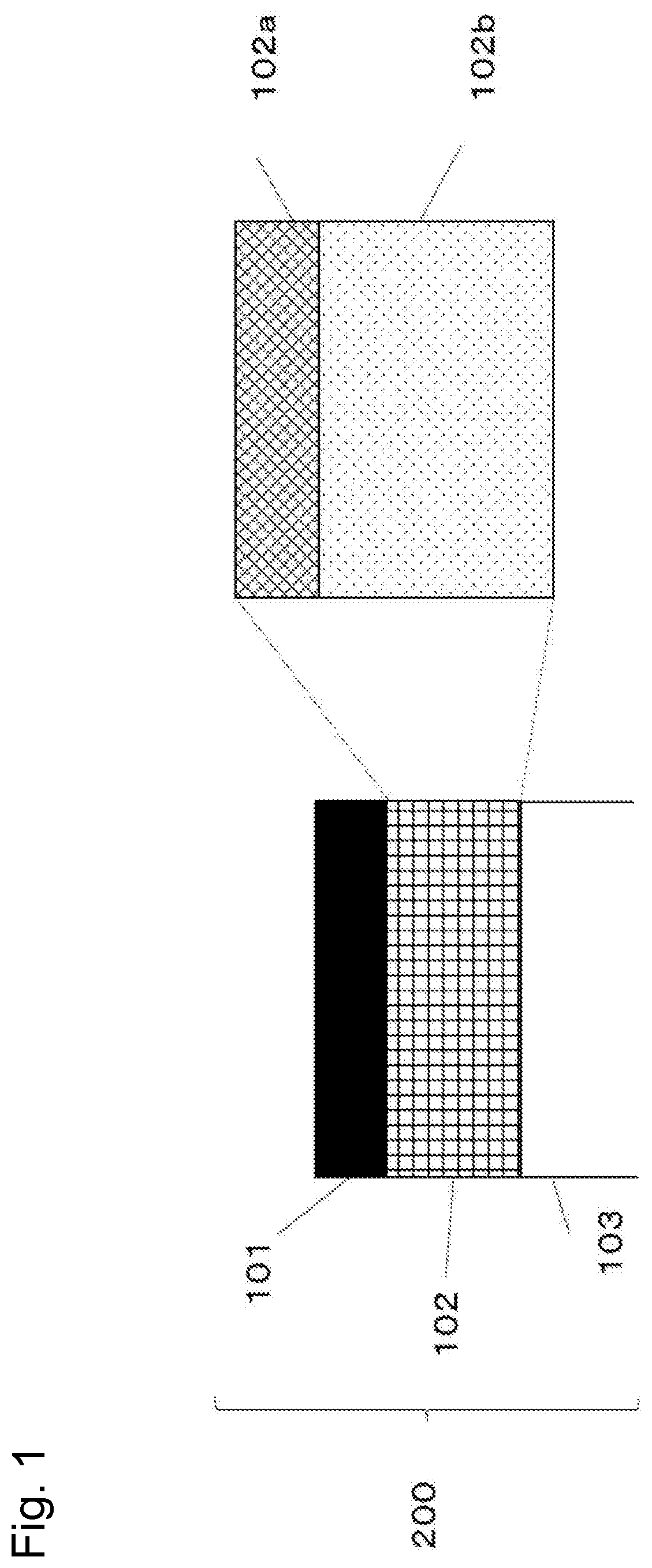
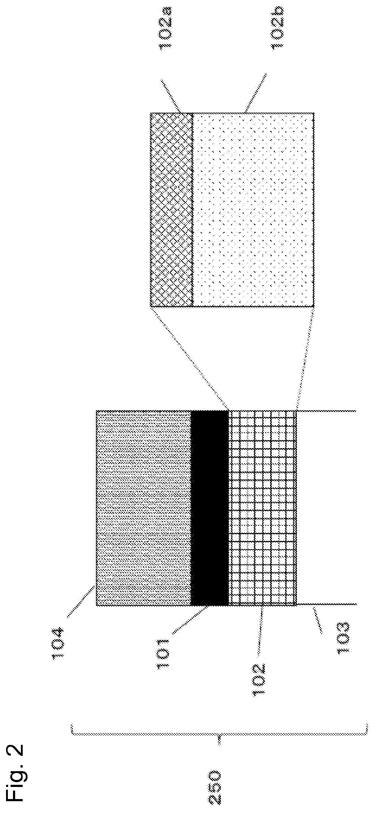
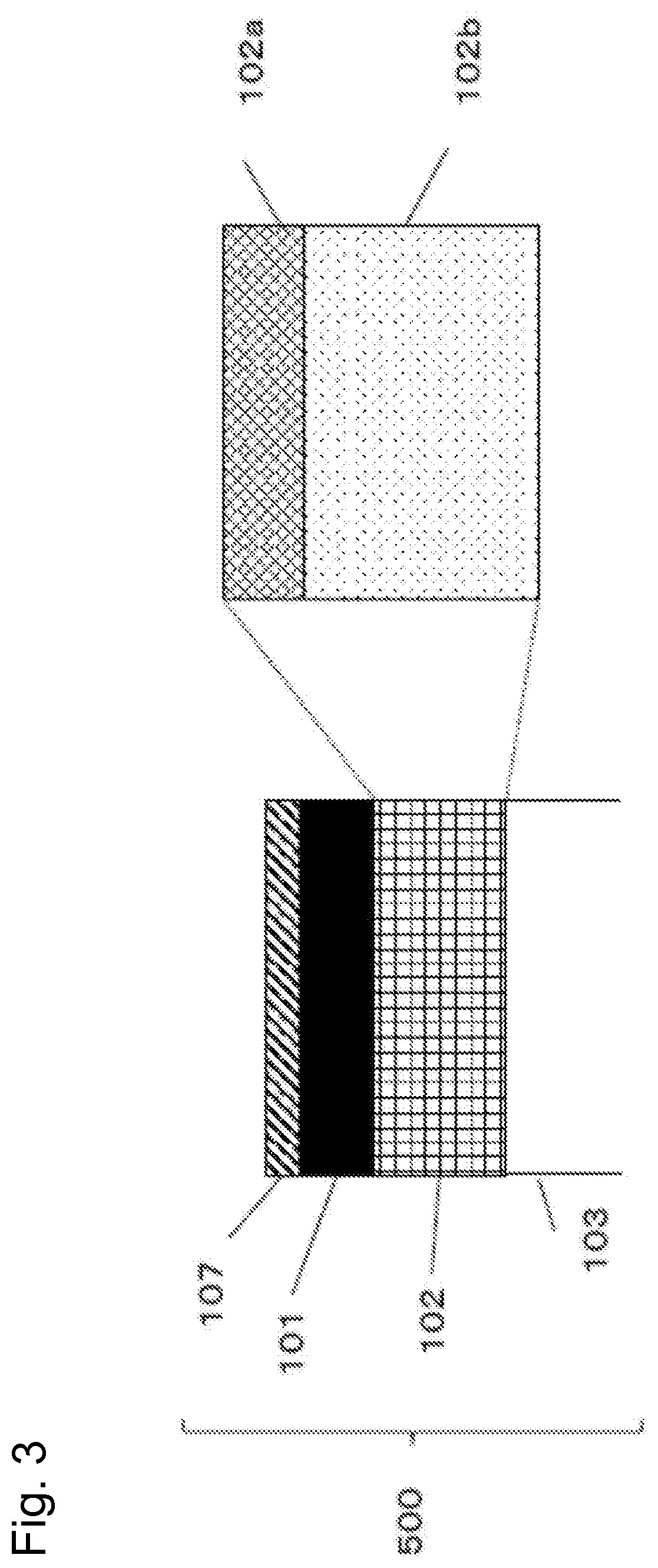
[0086]Refractive index n1 of first phase shift film 102b: 2.60

[0087]Extinction coefficient k1 of first phase shift film 102b: 0.35

[0088]Refractive index n2 of second phase shift film 102a: 1.85

[0089]Extinction coefficient k2 of second phase shift film 102a: 0.004

[0090]In order to verify the validity of the photomask blank according to the present invention, as a comparative example, wafer transfer simulation was also performed to a conventional phase shift...


PUM


Abstract

A photomask blank and a photomask having favorable wafer transfer characteristics and irradiation resistance. A photomask blank is for fabricating a photomask for an exposure wavelength of 193 nm, the photomask blank comprising: a light-transmissive substrate; a phase shift film formed on the light-transmissive substrate and providing phase shift effects of a light transmittance of at least 30% with respect to exposure light; and a light-shielding film formed on the phase shift film. The phase shift film is constituted by lamination of: a first phase shift film (that uses a silicon nitride-based material, has a refractive index n1 of 2.5 to 2.7, and an extinction coefficient k1 of 0.2 to 0.4; and a second phase shift film that uses a silicon oxynitride-based material, has a refractive index n2 of 1.55 to 2.20, and an extinction coefficient k2 greater than 0 but no greater than 0.1.

Description

CROSS-REFERENCE TO RELATED APPLICATIONS[0001]The present application is a continuation application of International Application No. PCT / JP2018 / 014059, filed Apr. 2, 2018, which claims priority to Japanese Patent Application No. 2017-073498, filed Apr. 3, 2017, the contents of all of these applications are incorporated herein by reference in their entirety.TECHNICAL FIELD[0002]The present invention relates to a photomask blank, a photomask and a photomask manufacturing method used for fabricating semiconductor devices and so on.BACKGROUND ART[0003]As a technique for forming a fine pattern image on a resist material, a photomask manufacturing device and manufacturing method is known where an original pattern is drawn on a photomask blank coated with a photoresist, which is subjected to heat treatment after exposure and developed thereafter to fabricate a resist pattern. Then, a light shielding film and a phase shift film are etched using the resist pattern as a mask. The light shieldi...

Claims


Application Information

Patent Timeline
IPC IPC(8): G03F1/32G03F1/80G03F1/76
CPCG03F1/80G03F1/32G03F1/76G03F1/50G03F7/70958
Inventor SAKAMOTO, YOSHIFUMIKOJIMA, YOSUKENAGATOMO, TATSUYA
Owner TOPPAN PHOTOMASK CO LTD
Learn More