Isolating Decoupler
- Summary
- Abstract
- Description
- Claims
- Application Information
AI Technical Summary
Benefits of technology
Problems solved by technology
Method used
Image

Examples
first embodiment
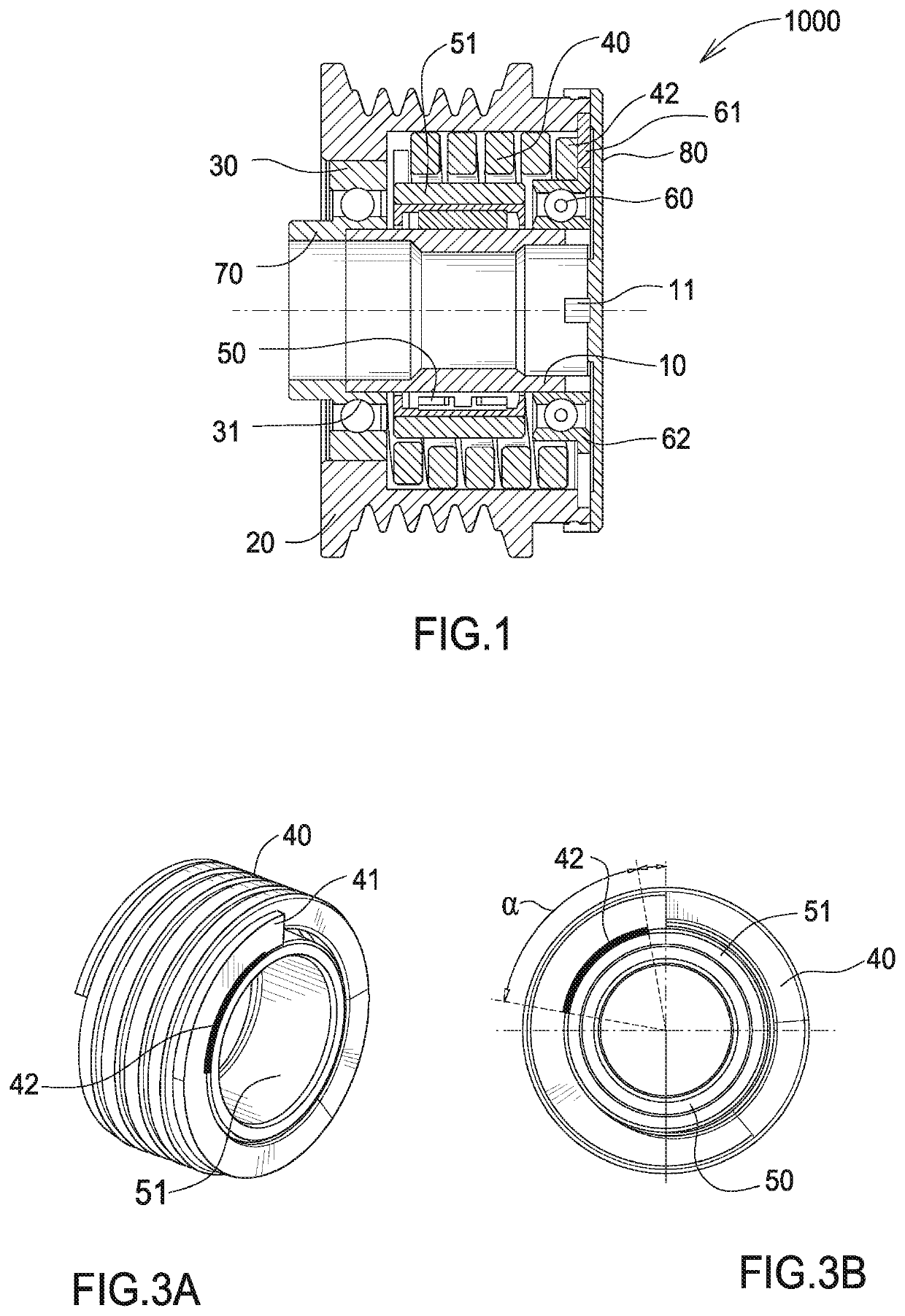
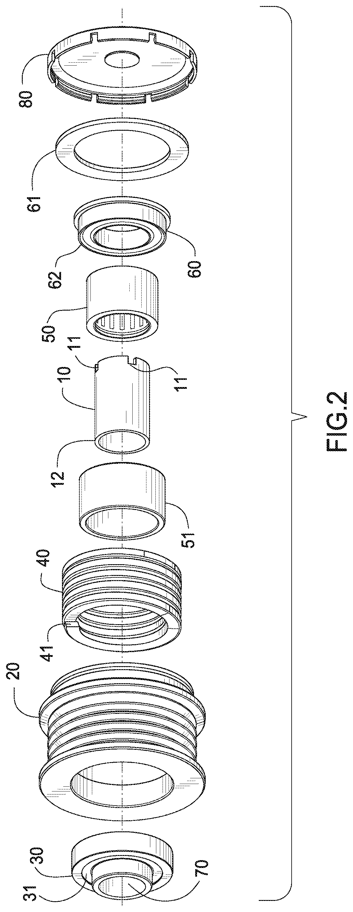
[0043]FIG. 1 is a cross section of a Isolating decoupler 1000 comprises shaft 10, pulley 20, ball bearing 30, torsion spring 40, one-way clutch 50 and bearing 60. Ball bearing 30 may also comprise a needle bearing.
[0044]Pulley 20 is journalled to shaft 10 through bearing 30 and bearing 60. Torsion spring 40 is engaged between pulley 20 and one-way clutch carrier 51. Dust cover 80 prevents debris from entering the device.
[0045]An outer race 62 of bearing 60 comprises a radially extending flange 61. Flange 61 is welded to bearing race 62 and is also welded to pulley 20.
[0046]End 42 of torsion spring 40 is welded to flange 61. The other end 41 of torsion spring 40 is welded to clutch carrier 51. Clutch carrier 51 is press fit on one-way clutch 50. One-way clutch 50 is an anti-rotation feature that prevents rotation of the pulley in a predetermined direction while allowing rotation of the pulley in the opposite direction.
[0047]Receiving portion 11 is used to hold shaft 10 in a fixed po...
second embodiment
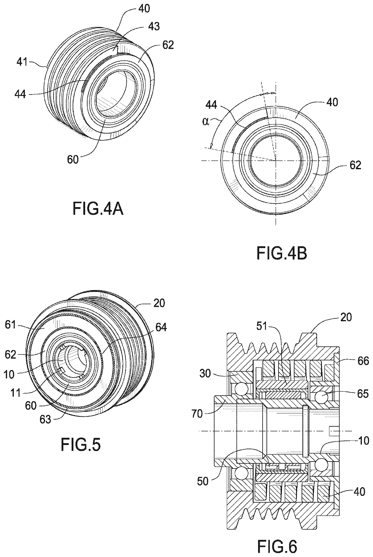
[0056]FIG. 6 is a cross-section view of a In this embodiment the inner race of ball bearing 65 is an integral part of shaft 10.
[0057]“L” shaped flange 66 is press fit onto the outer race of bearing 65.
[0058]FIG. 7 is an exploded view of FIG. 6.
[0059]FIG. 8a is a perspective view of a weld detail. Weld bead 42 attaches end 41 to carrier 51. Weld 42 may be accomplished using methods known in the welding arts such as MIG, SMAW, GMAW, TIG and laser welding. Bead 42 extends through an angle a of approximately 70 degrees in circumference, however, the length of the weld bead may vary between approximately 45 degrees and approximately 90 degrees depending on operational requirements.
[0060]FIG. 8b is a front view of a weld detail.
[0061]FIG. 9a is a perspective view of a weld detail. Weld bead 45 attaches end 43 to outer flange 66. The weld may be accomplished using methods known in the welding arts such as MIG, SMAW, GMAW, TIG and laser welding. Weld 45 extends through approximately 70 deg...
third embodiment
[0064]FIG. 11 is a cross-section view of a In this embodiment bearing assembly 600 is threadably engaged with shaft 100. Torsion spring 400 is engaged between flange 68 and carrier 51. Pulley 21 is journalled to shaft 100 through bearing 20.
[0065]Bearing assembly 600 is threaded into shaft 100. Bearing assembly 600 comprises a bearing 601, carrier 602 and dust cover 603. Bearing 601 is press fit onto carrier 602. One end of carrier 602 comprises threaded projection 604. Threaded projection 604 engages threaded receiver 101 of shaft 100. A tool such as a ratchet (not shown) can engage portion 605 to screw bearing assembly 600 into shaft 100. Pulley 21 is journalled to shaft 100 on bearing 601.
[0066]FIG. 12 is a perspective of a weld detail. Weld bead 420 attaches end 410 to carrier 51. Weld 420 may be accomplished using methods known in the welding arts such as MIG, SMAW, TIG and laser welding. Weld 420 extends through approximately 70 degrees in circumference. However, the length o...
PUM
 Abstract
Description
Claims
Application Information
 - R&D
- Intellectual Property
- Life Sciences
- Materials
- Tech Scout
- Unparalleled Data Quality
- Higher Quality Content
- 60% Fewer Hallucinations
Browse by: Latest US Patents, China's latest patents, Technical Efficacy Thesaurus, Application Domain, Technology Topic, Popular Technical Reports.
© 2025 PatSnap. All rights reserved.Legal|Privacy policy|Modern Slavery Act Transparency Statement|Sitemap|About US| Contact US: help@patsnap.com